background image


 i.MX35 PDK 1.5 Linux Quick Start Guide, Rev 1.5

 Freescale 

Semiconductor 

3-4 

3.2


Connect Development Platform to PC; Run Preloaded 

Image 

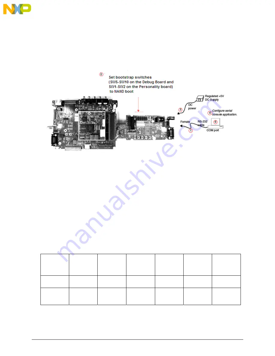
Figure 3-5 illustrates the components and locations for the steps that follow. 


To connect the 3-Stack platform to your host PC, use these steps: 

1.


Connect one end of an RS-232 serial cable (included in the kit) to a serial port connector 
(CON4) on the Debug board and connect the other end to a COM port on the host PC.  


Configure SW4-1 to ON.  


Make sure that SW4-8 is ON, to supply power to all three boards. 


Configure SW4-2 to OFF. 

2.


Confirm that the Bootstrap switches (SW5-SW10 on the Debug Board and SW1-SW2 on 
the Personality board) are set for NAND boot. See Table 3.1 and Table 3.2. 

Table 3.1 Boot Mode Setting 

Boot 

Mode 

Device 

SW5 SW6 SW7 

 SW8 SW9 SW10 

UART/USB 
bootloader 

X 0 0 0 1 1 

8-bit NAND 
Flash(2KB 
page) Ext  

X 1 0 0 1 0 


Figure 3-5 Connecting the Platform to the PC 

Summary of Contents for i.MX35

Page 1: ...i MX35 PDK 1 5 Linux Quick Start Guide Standard Base Doc Number 926 78233 Rev 1 5 04 2009...

Page 2: ...roducts for any particular purpose nor does Freescale Semiconductor assume any liability arising out of the application or use of any product or circuit and specifically disclaims any and all liabilit...

Page 3: ...m Assemble 3 Boards 3 2 3 1 1 Connect Personality Board to Debug Board 3 2 3 1 2 Connect CPU Board to Personality Board 3 3 3 2 Connect Development Platform to PC Run Preloaded Image 3 4 3 3 Building...

Page 4: ......

Page 5: ...and one BSP for Linux operating systems These BSPs contain drivers optimized for multimedia operations using the i MX35 and MC13892 devices Freescale s 3 Stack Platform System consists of three small...

Page 6: ...100 Base T Ethernet connector Current measure connectors 71 400 mm x 174 900 mm Battery Support 4 2 V 2400mAh Battery power supply and Battery Charging Function LCD Display 7 inch TFTLCD display pane...

Page 7: ...MLB signal An audio codec header for connect audio feature card Serial Port Two RS 232 interfaces with DB 9 connectors one is driven by UART channel internal to the MX35 and supports DCE with optional...

Page 8: ...board to either of the other two boards Connect the CPU board to a Personality board for running demos no Debug board is needed to run demos that do not use serial console commands Connect the CPU boa...

Page 9: ...Freescale Semiconductor i MX35 PDK 1 5 Linux Quick Start Guide Rev 1 5 1 5 1 3 Debug Board Figures 1 3 and 1 4 illustrate the top and bottom of the Debug Board Figure 1 3 Debug Board Top...

Page 10: ...1 5 Freescale Semiconductor 1 6 Table 1 2 Debug Board Physical Features Type Physical Features Switches S1 Power button S2 Debug board reset button S3 System reset switch S4 Power on switch SW4 Enable...

Page 11: ...PLD JTAG connector CN3 Personality board CPLD JTAG connector Reserved CN74 500 pin connector to Personality board CON4 UART DCE DB9 female connector LEDs D1 D8 LEDs for CPLD debug D9 LED for debug boa...

Page 12: ...Quick Start Guide Rev 1 5 Freescale Semiconductor 1 8 Table 1 4 Boot Mode Setting SW5 SW10 Boot Mode Device SW5 Boot4 SW6 Boot3 SW7 SW8 SW9 SW10 UART USB bootloader X 0 0 0 1 1 8 bit NAND Flash 2KB p...

Page 13: ...PDK 1 5 Linux Quick Start Guide Rev 1 5 1 9 Figure 1 6 Personality Board bottom 1 4 Personality Board Figures 1 5 and 1 6 illustrate the top and bottom of the Personality Board respectively Figure 1 5...

Page 14: ...nnector J14 CPT 7 WVGA LCD connector J16 FEC connector J18 Type A high speed USB connector J20 Audio input connector J21 TV Y Pr Pb input connector J22 Touch screen connector J23 Touch panel connector...

Page 15: ...inux Quick Start Guide Rev 1 5 1 11 Table 1 6 Personality Boot Mode Settings Boot Mode Device SW1 SW2 UART USB Bootstrap All OFF IGNORED NAND Flash All OFF 1 4 and 5 ON the rest OFF SD MMC All OFF 1 a...

Page 16: ......

Page 17: ...Figure 2 1 illustrates the components of the i MX35 PDK 1 5 development kit Table 2 1 describes the kit content and Table 2 2 describes the DVD content Verify that all the items are contained in the p...

Page 18: ...2 DVD Content Item Description i MX35 PDK 1 5 Product Brief Data sheets for the 3 Stack Platform s non Freescale components i MX Advanced ToolKit Release Notes i MX Advanced ToolKit User s Guide i MX3...

Page 19: ...33 MHz Pentium II or later processor 2 GHz processor recommended 512 MB of RAM 1 GB recommended 1 GB of available space required on system drive 10 GB of available hard disk space DVD ROM drive 1024x7...

Page 20: ......

Page 21: ...opment platform Personality board CPU board Debug board or a demonstration platform Personality board CPU Personality board CPU board and how to connect the 3 Stack platform to your PC See Figure 3 1...

Page 22: ...res in Build a Demo Platform Assemble 2 Boards on page 20 Figure 3 2 illustrates the maximum angle at which the boards can be separated 3 1 Building a Development Platform Assemble 3 Boards This secti...

Page 23: ...Start Guide Rev 1 5 3 3 3 1 2 Connect CPU Board to Personality Board After connecting the Personality board to the Debug board connect the CPU board to the underside of the Personality board Figure 3...

Page 24: ...ial port connector CON4 on the Debug board and connect the other end to a COM port on the host PC Configure SW4 1 to ON Make sure that SW4 8 is ON to supply power to all three boards Configure SW4 2 t...

Page 25: ...r host PC with the following configuration Table 3 3 Serial Console Configuration Baud Rate 115200 Data Bits 8 Parity None Stop Bits 1 Flow Control None 5 On the Debug board switch the power switch S4...

Page 26: ...ty board Use these steps 1 Connect the regulated 5V power supply to the appropriate power adapter 2 Plug the 5V line into the J12 5V POWER JACK connector on the Personality board Figure 3 6 Figure 3 6...

Page 27: ...ptions to set preferences for appearance language volume display and other settings The Linux Demo Image requires the use of the Multimedia Applications and Settings tabs Figure 4 1 illustrates the Ad...

Page 28: ...ick Start Guide Rev 1 5 Freescale Semiconductor 4 2 3 Create a serial connection 8N1 at 115200 as shown in Figure 4 1 which illustrates the configuration for HyperTerminal software Figure 4 1 Configur...

Page 29: ...with pictures or other multimedia content you may use the PDK to view its content To use the SD Card follow these steps 1 Insert the SD Card in the MMC SD Card slot which is located in the lower part...

Page 30: ...un the applications First see Supported Codecs for a description of the software packages supported by the system 4 3 1 Running the Video Application The Video application enables you to view video fi...

Page 31: ...Select the Picture Viewer Application The mnt flc Pictures folder is displayed showing the files previously saved Click on a picture to view it 3 When a picture is selected options are displayed to m...

Page 32: ...h the adif format Play Pause Stop Seek metadata query mfw_h264decoder H264 baseline decoder Play Pause Stop Seek metadata query mfw_mpeg4decoder MPEG 4 H263 simple profile decoder Play Pause Stop meta...

Reviews: