background image

USER'S MANUAL

CAUTION

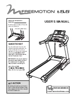
Read all precautions and instruc-
tions in this manual before using
this equipment. Save this manual
for future reference.

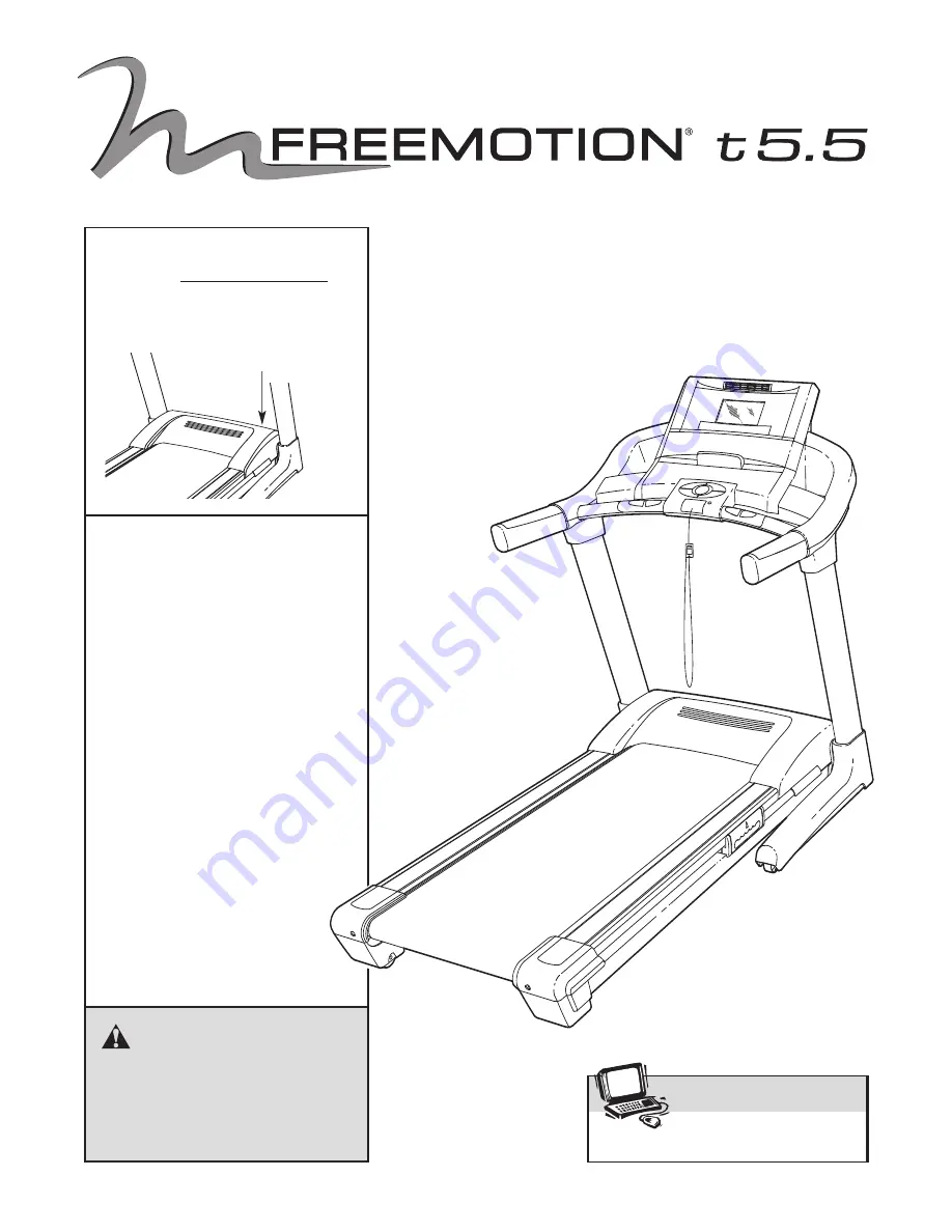
Serial Number Decal

Model No. SFTL82207.0 
Serial No. 

Write the serial number in the space
above for reference.

QUESTIONS?

As a manufacturer, we are com-
mitted to providing complete cus-
tomer satisfaction. If you have
questions, or if parts are damaged
or missing, 

PLEASE DO NOT

CONTACT THE STORE; please
contact Customer Care. 

IMPORTANT: You must note the
product model number and ser-
ial number (see the drawing
above) before contacting us.

CALL TOLL-FREE:  

1-866-799-8946

Mon.–Fri. 8 a.m.–5 p.m. MST

Visit our website at

www.weslo.com

new products, prizes,

fitness tips, and much more!

V

Visit our website at

www.proform.com

new products, prizes,

fitness tips, and much more!

Visit our website at

www.healthrider.com

new products, prizes,

fitness tips, and much more!

V

Visit our website at

www.freemotionfitness.com

V

Summary of Contents for SFTL82207.0

Page 1: ...s or if parts are damaged or missing PLEASE DO NOT CONTACT THE STORE please contact Customer Care IMPORTANT You must note the product model number and ser ial number see the drawing above before contacting us CALL TOLL FREE 1 866 799 8946 Mon Fri 8 a m 5 p m MST Visit our website at www weslo com new products prizes fitness tips and much more Visit our website at www proform com new products prize...

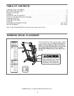
Page 2: ...D WARRANTY Back Cover Note An EXPLODED DRAWING is attached in the center of this manual 2 The warning decals shown here have been applied in the locations shown If a decal is missing or il legible call the telephone number on the front cover of this manual and request a free replace ment decal Apply the decal in the location shown Note The decals may not be shown at ac tual size WARNING DECAL PLAC...

Page 3: ...surge suppressor see your local FREEMOTION dealer or call the tele phone number on the front cover of this man ual and order part number 146148 or see your local electronics store 13 Failure to use a properly functioning surge suppressor could result in damage to the con trol system of the treadmill If the control sys tem is damaged the walking belt may change speed accelerate or stop unexpectedly...

Page 4: ...ding con ductors location of antenna discharge unit connection to grounding electrodes and re quirements for the grounding electrode 29 An outside antenna system should not be lo cated in the vicinity of overhead power lines or other electric light or power circuits or where it can fall into such power lines or cir cuits When installing an outside antenna sys tem extreme care should be taken to ke...

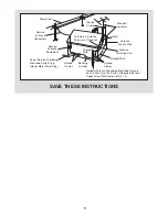
Page 5: ...und Wire Ground Wire Antenna Discharge Unit To External Antenna Terminal of Treadmill Mast Service Entrance Equipment Power Service Grounding Electrode System e g Interior Metal Water Pipe Service Entrance Conductors Optional Antenna Grounding Electrode Driven 8 Feet 2 44m Into The Earth If Required By Local Codes See NEC Section 810 21 f ...

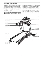
Page 6: ...ll If you have questions after read ing this manual please see the front cover of this man ual To help us assist you note the product model number and serial number before contacting us The model number and the location of the serial number decal are shown on the front cover of this manual Before reading further please look at the drawing below and familiarize yourself with the labeled parts BEFOR...

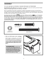
Page 7: ...his manual The number following the parenthe ses is the quantity needed for assembly Note Some small parts may have been preassembled If a part is not in the parts bag check to see if it has been preassembled To avoid damaging plastic parts do not use power tools for assembly w 123 2 1 2 Silver Screw 48 1 3 4 Tek Screw 58 4 Spacer Screw 60 2 4 1 2 Bolt 78 4 Washe nsion Leg 106 4 Upright Star Washe...

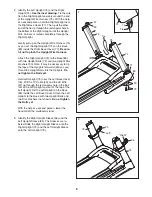
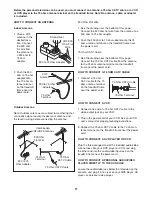
Page 8: ...Star Washers 90 Note It may be necessary to tip the tops of the Uprights forward slightly as you thread the Upright Bolts into the Uprights Do not tighten the Bolts yet Hold Left Upright 73 near the Left Base Cover 76 Pull the TV Cable 49 and the AV Wire 97 up through the rectangular hole in the bot tom of the Left Upright and out of the top of the Left Upright Set the Left Upright on the Base 83 ...

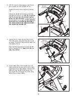
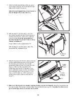
Page 9: ...WER IS TURNED ON 71 Console Assembly 4 75 Tie 74 5 Connect the TV Cable 49 and the AV Wire 97 to the cables extending from the console assembly Then insert the connectors down into the Uprights 73 74 Next insert the brackets on the Handrails 99 into the Uprights 73 74 Make sure that no wires are pinched 49 73 97 5 74 99 6 Finger tighten three Handrail Bolts 64 with three Upright Star Washers 90 in...

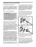
Page 10: ...e hex key is used to adjust the walking belt see page 27 To protect the floor or car pet from damage place a mat under the treadmill 75 Ohm Antenna Terminal 7 Slide the Right Upright Sleeve 96 up against the console assembly Attach the Right Upright Sleeve with two 3 4 Screws 4 Attach the Left Upright Sleeve not shown to the Left Upright 73 in the same way 73 74 4 96 4 7 Audio Video Input 115 8 Wi...

Page 11: ...wer cord HOW TO CONNECT A VCR 1 Connect one end of a 75 ohm CATV cable to the video output jack on your VCR 2 Plug in the power cord of your VCR See your VCR user s manual for proper grounding instructions 3 Connect the 75 ohm CATV cable to the 75 ohm an tenna terminal on the treadmill frame near the power cord HOW TO CONNECT A DVD PLAYER OR VCR Plug the three pronged end of the included audio vid...

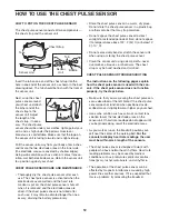
Page 12: ...r container that may trap moisture Do not expose the chest pulse sensor to direct sunlight for extended periods of time do not expose it to temperatures above 122 F 50 C or below 14 F 10 C Do not excessively bend or stretch the sensor unit when using or storing the chest pulse sensor Clean the sensor unit using a damp cloth never use alcohol abrasives or chemicals The chest strap may be hand washe...

Page 13: ...c tion or break down grounding provides a path of least resistance for electric current to reduce the risk of elec tric shock This product is equipped with a cord having an equipment grounding conductor and a grounding plug Plug the power cord into a surge suppressor and plug the surge suppressor into an appropriate outlet that is properly installed and grounded in accordance with all local codes ...

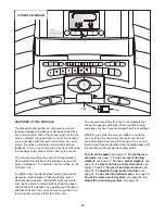
Page 14: ...trols the speed and incline of the treadmill as it guides you through an effective workout You can even create your own cus tom workouts and save them for future use The console also offers four heart rate workouts that control the speed and incline of the treadmill to help you keep your heart rate near target heart rate settings Whether you select the manual mode or a workout you can enjoy the sh...

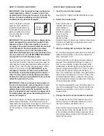
Page 15: ...ay speed and distance in either miles or kilometers To find out which unit of measurement is selected or to change the unit of mea surement see THE INFORMATION MODE on page 23 For simplicity all instructions in this section refer to miles HOW TO USE THE MANUAL MODE 1 Insert the key into the console See HOW TO TURN ON THE POWER to the left 2 Select the manual mode Each time the key is inserted the ...

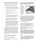
Page 16: ...splay mode To reset the console press the Stop button re move the key and then reinsert the key 6 Measure your heart rate if desired To measure your heart rate using the chest pulse sensor see page 12 Note If you use the handgrip pulse sensor and the chest pulse sensor at the same time the console will not display your heart rate accu rately Before using the handgrip pulse sensor remove the sheets...

Page 17: ... Speed or Incline buttons During an event training workout the screen will show the number of miles or kilometers still to be walked or run To stop the workout at any time press the Stop button To restart the workout press the Start but ton The walking belt will begin to move at 1 mph Adjust the speed of the walking belt as desired by pressing the Speed increase or decrease button or one of the nu...

Page 18: ... 1 9 10 101 62 60 105 56 58 4 6 47 35 62 10 57 7 8 7 39 38 40 29 54 29 59 12 15 16 19 18 51 38 53 4 4 17 32 35 33 33 133 37 18 17 19 16 15 2 2 13 29 11 53 38 52 52 24 38 34 4 4 4 4 13 46 29 4 4 4 30 30 9 8 61 61 105 56 48 106 107 108 4 44 4 4 4 45 45 1 50 98 55 33 55 55 115 100 117 38 113 38 119 118 36 68 84 EXPLODED DRAWING Model No SFTL82207 0 R0907A ...

Page 19: ... 4 82 81 4 4 4 4 4 80 4 49 76 77 4 4 4 4 90 72 90 72 90 41 4 4 4 4 110 4 111 112 102 97 97 49 116 116 135 80 4 4 4 4 4 4 4 120 121 66 13 13 71 122 69 123 46 13 124 126 4 4 125 109 129 130 13 135 78 78 78 78 78 103 78 78 5 5 5 13 13 13 13 127 132 132 132 132 EXPLODED DRAWING Model No SFTL82207 0 R0907A EXPLODED DRAWING Model No SFTL82207 0 R0907A ...

Page 20: ...nd or incline setting may be pro grammed for consecutive segments When only three seconds remain in the first seg ment of the workout a series of tones will sound If the speed and or the incline of the treadmill is about to change the new speed and or incline set ting will appear on the screen to alert you When the first segment ends the arrow below the work out profile will move one position to t...

Page 21: ...can be programmed for each seg ment To program a speed setting and an incline setting for the first segment simply adjust the speed and incline of the treadmill as desired by pressing the Speed and Incline buttons When the first segment of the workout ends a se ries of tones will sound and the current speed set ting and the current incline setting will be saved in memory Program a speed setting an...

Page 22: ...out see step 4 on page 18 If desired you can redesign the workout while using it To change the speed setting or the in cline setting for the current segment simply press the Speed or Incline buttons When the current segment ends the new setting will be saved in mem ory To increase the length of the workout first wait until the workout is completed Then press the Start button and program speed and ...

Page 23: ...d and incline settings of the workout Hold the handrails and begin walking Heart rate workout 1 is divided into several one minute segments The same target heart rate set ting is programmed for all segments except for the first two segments Heart rate workouts 2 3 and 4 are divided into 30 one minute segments One tar get heart rate setting is programmed for each seg ment Note The same target heart...

Page 24: ...ce or the Console MP3 mode by pressing the TV Power button repeatedly If you have connected an antenna a 75 ohm CATV cable or a VCR to the 75 ohm antenna ter minal on the treadmill select the Tuner source If you have plugged a DVD player or VCR into the three audio video RCA jacks select the RCA source If you have connected a personal audio video player to the audio video jack below the television...

Page 25: ...vision When you press the TV Power button the brightness level indicator will appear on the television screen Press the Volume VOL buttons to adjust the brightness setting if desired Next press the Channel CHAN buttons until the contrast color sharpness or hue level indicator ap pears Adjust the settings if desired by pressing the Volume buttons 3 Press the TV Power button again and add or delete ...

Page 26: ...adjust the volume on the console by pressing the Volume VOL increase and decrease buttons If you are using a personal CD player or DVD player and the CD or DVD skips set the CD player or DVD player on the floor or another flat surface instead of on the console HOW TO ADJUST THE CUSHIONING SYSTEM The treadmill features a cushioning system that re duces the impact as you walk or run on the treadmill...

Page 27: ...mill convert the treadmill to the stor age position as described above Make sure that the latch knob is locked in the storage position 1 Hold the handrails and place one foot against one of the wheels 2 Tilt the treadmill back until it rolls freely on the wheels Carefully move the treadmill to the desired location Never move the treadmill without tipping it back To reduce the risk of injury use ex...

Page 28: ...ipped To reset the circuit breaker wait for five minutes and then press the switch to the reset position PROBLEM The power turns off during use SOLUTION a Check the reset off circuit breaker see the drawing above If the circuit breaker has tripped wait for five minutes and then press the switch to the reset position b Make sure that the power cord is plugged in If the power cord is plugged in unpl...

Page 29: ...ng platform Be careful to keep the walking belt centered Then plug in the power cord insert the key and run the treadmill for a few min utes Repeat until the walking belt is properly tight ened c If the walking belt still slows when walked on please see the front cover of this manual PROBLEM The walking belt is off center or slips when walked on SOLUTION a If the walking belt is off center remove ...

Page 30: ...e sure that it is properly connected and adjusted for optimal reception See HOW TO CON NECT AN ANTENNA on page 11 b Check for the problems listed below and follow the applicable instructions Ignition black spots or horizontal streaks that appear or a picture that flutters or drifts Usually this is caused by interference from automobile ignition systems neon lamps electric drifts or other electric ...

Page 31: ... your goal is to strengthen your cardiovascular system you must perform aerobic exer cise which is activity that requires large amounts of oxygen for prolonged periods of time For aerobic ex ercise adjust the intensity of your exercise until your heart rate is near the highest number in your training zone WORKOUT GUIDELINES Warming up Start with 5 to 10 minutes of stretching and light exercise A w...

Page 32: ...ft Motor Bolt Top 41 1 AV Cover 42 1 Left Platform Cushion 43 1 Power Cord Bracket 44 1 Hood 45 4 Hood Clip 46 2 Grommet 47 1 Walking Belt 48 1 Frame 49 1 TV Cable 50 1 Right Platform Cushion 51 1 Right Rear Foot 52 4 Rear Wheel 53 2 Rear Wheel Bolt 54 1 Right Rear Endcap 55 4 Bracket Washer 56 2 Rear Roller Adjustment Bolt 57 1 Hex Key 58 1 Left Rear Foot 59 1 Left Rear Endcap 60 1 Rear Roller 61...

Page 33: ... Cover Fastener 115 1 Audio Video Wire Harness 116 2 Console Clamp 117 1 Upper Latch Bolt 118 1 Latch Knob 119 1 Latch Endcap 120 1 Left Pulse Grip 121 1 Right Pulse Grip 122 3 4 Ground Wire 123 1 Console TV Cable 124 1 Speaker Cover 125 1 Speaker 126 4 Speaker Screw 127 1 6 Wire Harness 128 2 Cushion Track 129 1 Chest Pulse Sensor 130 1 Chest Pulse Strap 131 1 4 Wire Harness 132 4 Base Pad Spacer...

Page 34: ...ove is authorized by ICON ICON is not responsible or liable for indirect special or consequential damages arising out of or in con nection with the use or performance of the product or damages with respect to any economic loss loss of property loss of revenues or profits loss of enjoyment or use costs of removal or installation or other consequential damages of whatsoever nature Some states do not...

Reviews: