background image

9

CAUTION:

After making any cable adjustment, pull the

handle using a light load and have someone make
sure that the cable is not derailed from a pulley or rub-
bing on a guard (see CABLE GUARDS on page 8).

INITIAL ADJUSTMENT

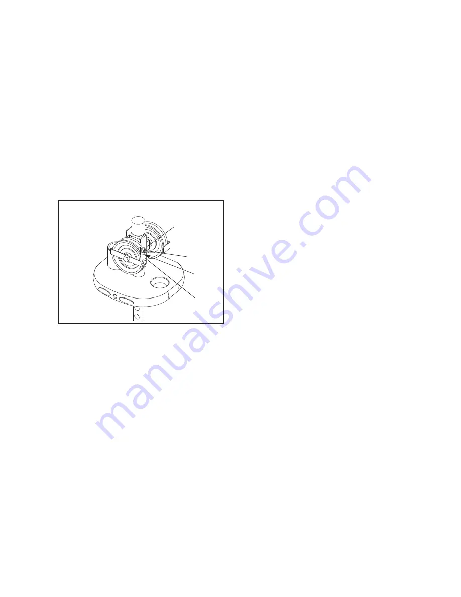
Top Weight Pulley Adjustment—

Tools required: 9/16" open or box-end wrench, 5/16"
Allen wrench 

1. Remove the access cover by pulling it free at the

bottom and then sliding it up until the two sets of
tabs release.

2. Loosen the nut holding the pulley block in the 

“U”-bracket. 

3. To increase the tension, slide the pulley block

down in the slot. To decrease the tension, slide
the pulley block up.

4. Tighten the nut and check the tension as

described in CABLE TENSION CHECK, on page
8. If necessary, readjust the pulley block. 

5. Replace the access cover.

ADDITIONAL ADJUSTMENTS

Handle End Adjustment—

Tools required: 1/8" Allen wrench, cable cutters, utili-
ty knife, torque wrench

Note:

Make this adjustment only if the pulley block

in the top weight has been fully adjusted to the bot-
tom of the slot and the cable requires more tension. 

Note:

This adjustment is only for increasing the

cable tension because it requires shortening the
cable. Only one end of the cable should be short-
ened.

1. Create slack in the cable by removing the weight

pin and pulling the handle out six to eight inches
(15–20 cm). Insert the weight pin into the third
weight plate and the tube on the bottom of the top
weight.

2. Push the black rubber cover off the aluminum

coupler and slide the cover up the cable to con-
tact the pulley in the swivel arm.

3. Loosen the four oval-point, 1/4"-20-unc set

screws in the coupler and pull the cable free.

4. Cut off one inch (2.5 cm) of the cable end using

cable cutters. 

Note: Using any other tool may

flatten or disrupt the end strands so that it
may be difficult to reinsert the cable into the
hole of the coupler.

5. Cut off one inch (2.5 cm) of the black cable

sheath from the end of the cable.

6. Reinsert the cable and the sheath into the coupler

so that all of the bare cable is in the hole.

7. Retighten the four set screws into the threaded

holes. Tighten the set screws equally until they
contact the cable. Then, tighten each screw alter-
nately 1/4 turn, until all are set to 85 inch-pounds
(9.6 Newton-meters).

8. Slide the rubber cover over the coupler, remove

the weight pin, and lower the handle. 

9. Check for proper tension on the cable as described

in CABLE TENSION CHECK, on page 8.

Pulley

Block

Nut

Slot

“U”-bracket

CABLE ADJUSTMENTS

Summary of Contents for GZFM6024.0

Page 1: ...anual for future reference Model No GZFM6024 0 Serial No Write the serial number in the space above for future reference Serial Number Decal inside tower QUESTIONS At FreeMotion Fitness we are committed to providing com plete customer satisfaction If you have questions see HOW TO CONTACT CUSTOMER CARE on the back cover of this manual OWNER S MANUAL ...

Page 2: ...IMPORTANT PRECAUTIONS 3 WARNING DECAL PLACEMENT 4 BEFORE YOU BEGIN 5 ADJUSTMENTS 6 MAINTENANCE 7 CABLE DIAGRAM 11 PART LIST 12 EXPLODED DRAWING 13 HOW TO CONTACT CUSTOMER CARE Back Cover TABLE OF CONTENTS ...

Page 3: ...ine irregularity to facility staff immedi ately 10 Make sure the weight pins are completely inserted into the weight plates before exercising 11 Make sure the handles are attached securely before each use of the strength machine 12 Check all cables cable connections and pul leys before each use of the strength machine Make sure all parts are properly tightened Replace any worn parts immediately 13...

Page 4: ...gible see HOW TO CONTACT CUSTOMER CARE on the back cover of this manual to order a free replacement decal Apply the decal in the location shown 4 DO NOT USE MACHINE FROM THIS SIDE WARNING Decal 2 Shown at 70 GZ7003 Decal 5 Shown at 85 Decal 4 Decal 7 Shown at 50 7 Inside the access cover Decal 6 GZ7026 Decal 3 6 3 5 5 5 1 1 2 3 4 Decal 1 GZ7008 ...

Page 5: ...build dramatic muscle size and strength improve your cardiovascular system or train muscles for precise patterns of movement the DUAL CABLE CROSS strength machine will help you to achieve the specific results you want For your benefit read this manual carefully before using the strength machine If you have questions after reading this manual see HOW TO CONTACT CUSTOMER CARE on the back cover of th...

Page 6: ...Make sure that the weight pin is fully inserted into the weight stack ADJUSTING THE ARMS To change the position of an arm pull the adjustment knob out and move the arm to the desired position Reengage the knob into the adjustment bracket ADJUSTING THE ARM BRACKETS To change the position of an arm bracket step on the pivot adjustment pedal to disengage the pin not shown and move the arm bracket to ...

Page 7: ... for difficult stains Rub the area gently using a soft cloth damp ened with rubbing alcohol Rinse thoroughly using a water dampened cloth to remove alcohol residue CAUTION When using any cleaning product try it first in an inconspicuous place to ensure there is no damage to the material Follow directions and adhere to the safety precautions of the manu facturer of each cleaning agent used FreeMoti...

Page 8: ...lubricants CABLE TENSION CHECK 1 Insert the weight pin into the top weight plate 2 Slowly raise and lower the top weight by normal machine use The top weight should come to rest just on top of the second weight when the handle is returned to the resting position If there is too much tension on the cable the top weight will not rest on the second weight and it may be difficult to insert the weight ...

Page 9: ... shortening the cable Only one end of the cable should be short ened 1 Create slack in the cable by removing the weight pin and pulling the handle out six to eight inches 15 20 cm Insert the weight pin into the third weight plate and the tube on the bottom of the top weight 2 Push the black rubber cover off the aluminum coupler and slide the cover up the cable to con tact the pulley in the swivel ...

Page 10: ...with the other bushing and weight insert 7 Replace the top weight on top of the weight stack 8 Reattach the U bracket to the top weight cou pler 9 Clean and lubricate the guide rods by wiping them with a soft cloth containing a light weight motor oil 10 40 or straight 30 weight Apply only a light coating over the entire length Note Do not use Teflon or Silicone based lubricants 10 Reattach the gui...

Page 11: ...the cable guards have been assembled correctly If the cables have not been correctly routed the strength machine will not function properly and damage may occur The numbers show the correct route of each cable Make sure that the cable guards do not touch or bind the cables 1 2 3 4 5 6 8 9 1 7 4 2 3 5 6 7 1 1 2 2 8 9 11 ...

Page 12: ...r 47 4 3 8 16 Jamnut 48 2 Cable Bearing 49 2 Eyebolt 50 2 1 1 8 Internal Retainer Ring 51 2 1 Nut 52 2 1 Washer 53 1 Right Pivot Pedal 54 1 Left Pivot Pedal 55 1 Top Tower Plate 56 28 Rivet 57 2 Tapered Pop Pin 58 1 Grip Cover 59 1 Left Pivot Plate 60 1 Right Pivot Plate 61 1 Left Pivot Adjustment Bracket 62 1 Right Pivot Adjustment Bracket 63 2 4 Single Cable Guard 64 1 Right Cable Cover 65 2 U b...

Page 13: ... 6 80 86 98 7 36 56 56 56 19 35 19 35 41 41 18 56 56 56 20 58 90 61 28 28 69 89 10 11 76 75 77 12 74 74 73 38 55 38 38 82 73 30 31 31 30 82 81 81 84 84 36 53 86 87 1 41 57 73 73 73 73 40 40 89 41 37 25 73 37 25 25 73 86 87 57 70 70 36 84 84 54 43 44 46 47 48 47 49 50 45 45 73 73 73 56 96 56 97 67 70 67 70 83 EXPLODED DRAWING A Model No GZFM6024 0 R0405A ...

Page 14: ...1 71 31 31 60 5 80 98 86 42 7 36 36 31 8 73 31 32 33 28 3 28 28 34 34 13 68 68 68 14 14 23 15 15 68 68 24 24 24 24 51 51 99 99 37 52 38 37 29 88 23 29 29 88 65 65 73 66 66 73 37 37 52 78 78 2 21 21 38 29 38 73 38 73 88 88 67 67 67 67 43 70 43 70 89 89 85 85 40 40 67 67 92 91 92 91 14 EXPLODED DRAWING B Model No GZFM6024 0 R0405A ...

Page 15: ... MODEL NUMBER of the product GZFM6024 0 The NAME of the product FREEMOTION DUAL CABLE CROSS strength machine The SERIAL NUMBER of the product see the front cover of this manual When ordering replacement parts please also give the KEY NUMBER and DESCRIPTION of the part s see the PART LIST and the EXPLODED DRAWING on pages 12 to 14 of this manual Customer Care 1 800 201 2109 Monday Friday 8 a m 5 p ...

Reviews: