Shield the diode from direct illumination. The current
should be below 50 pA under these conditions.
Now, let light from a flashlight or the like hit the diode
and observe that the photo current rises significant-
ly.
(Please note that this is an example of an experi-
ment, where hum from the mains can give weird re-
sults – the diode may rectify the induced noise vol-
tage, resulting in a overloaded input circuitry. Try to
move the experiment to another position in the
room.)
Examples of electrostatic induction
Prepare two 4415.00 metal plated ball on rod so
they have no electric charges on the rods.
Use two 4410.02 insulated rod; one connected to a
current limited, grounded high voltage supply and
the other connected to zero (
). Connect also the
negative pole of the power supply to zero.
Adjust the voltage to approximately 1.5 kV.
Note: Use only a high voltage supply with an
output current limiter (like our 3660.50) that
ensures it is not dangerous to touch the
equipment.
Place a 4425.00 faraday cup in the
Q
input of the
electrometer. Select the 5 nC range and press
Reset Q.
Charge one of the metalized balls and position it
inside the faraday cup – without touching it. The
charge on the ball draws a charge of approximately
same size but opposite sign up into the metal of the
cup. As the cup and the input were initially un -
charged, this must leave an equally large charge
inside the input, with the same sign as the charge on
the ball.
Lift the ball out of the cup – the meter returns to
zero.
Repeat this, but let the ball touch the inside of the
cup. The charges on the ball and the cup neutralize
each other, leaving the input charged. (This process
effectively transfers the charge from the ball to the
Q
input.)
The charge measured stays at this value, even when
the ball is removed.
Zero the instrument, and once again charge one of
the balls. The other ball is discharged to zero (
).
Now, let the two balls touch each other. For sym-
metry reasons, the charge is distributed evenly on
the two balls – which is demonstrated: Make one of
the balls touch the bottom of the faraday cup – the
meter goes halfway to the reading in the previous
experiment. Repeat this with the other ball without
zeroing – and now the meter reaches the same rea-
ding as before.
The plate capacitor
A 4315.10 or 4315.20 plate capacitor (resp. 15 or 22
cm) is used with 4316.00 dielectric (plates of PVC)
and 4316.80 distance pieces.
Place one plate horizontally by means of a retort
stand base and connect it to zero (
). Place the
other plate on top of it with either one or more
dielectric plates or distance pieces between.
A 4410.02 insulated rod is connected to a current
limited, grounded high voltage supply making it easy
to charge the upper capacitor plate with it. Connect
the negative pole of the high voltage supply to zero.
Another rod is connected to the
Q
input of the
electrometer. Set the range switch to 500 nC. Zero
the instrument.
Now, charge the upper capacitor plate with the tip of
the rod connected to the high voltage supply.
Remove the rod again and discharge the capacitor
through the electrometer with the tip of the other
insulated rod. If the pointer goes off scale, select a
lower voltage and try again. If on the other hand the
reading is too low to be precise, you may just repeat
the charge/discharge cycle. Count how many times
you repeat, and divide the reading by this number.
The charge (for one charging) is called
Q
.
Read the value of the high voltage
U
.
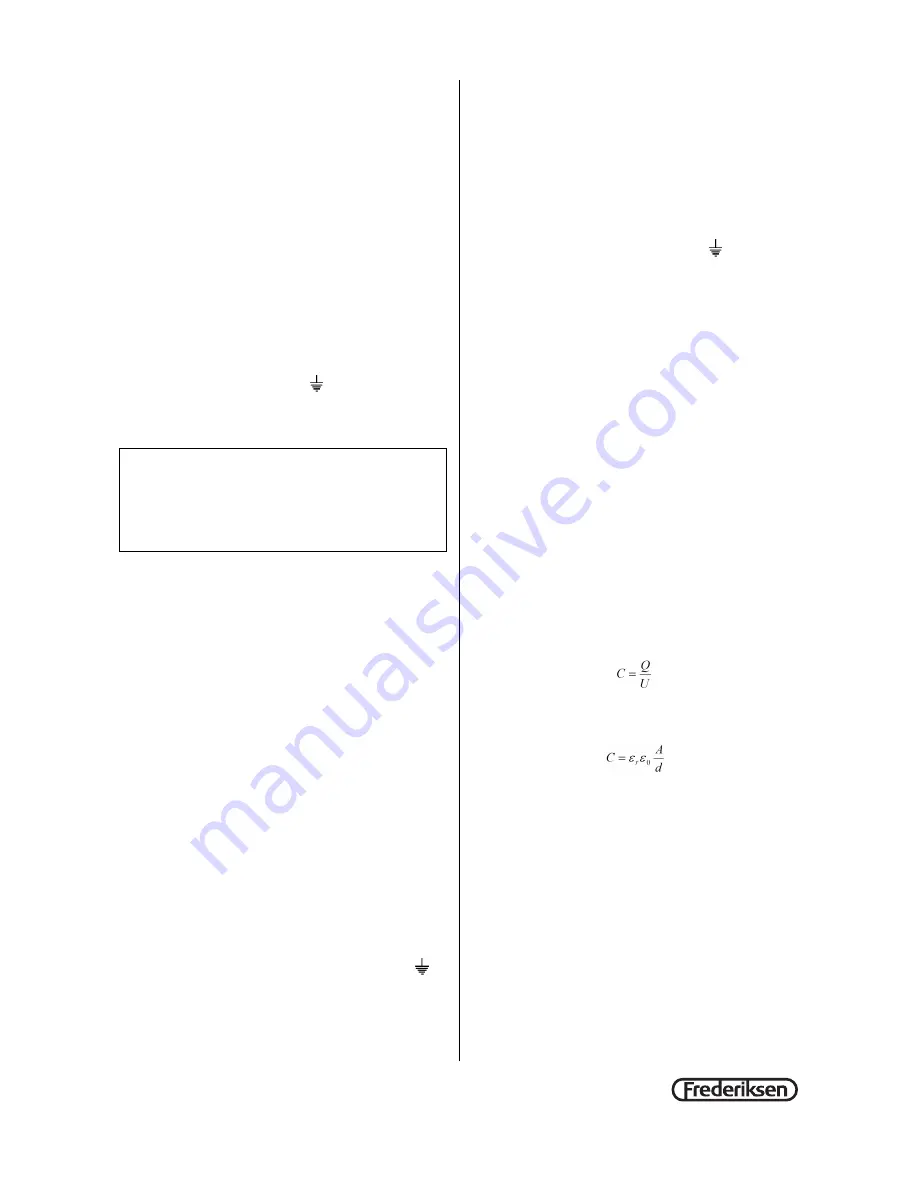
The capacitance
C
is given by
This should be compared with the theoretical
expression which is
Where
ε
r
is the relative permittivity for the dielectric
(1 for air)
ε
0
is the permittivity of vacuum,
A
is the
area of one of the plates and
d
is the distance
between them.
Repeat the experiment with varying distance (more
PVC plates or distance pieces).
Eventually the area dependency may be investi-
gated by switching between the 15 cm and the
22 cm plate capacitor.
Connecting the high voltage supply directly to
the electrometer must be avoided!
®


