REV03MAR99NB PRO3.P65
Page 3
INSTALLATION
Before proceeding with any installation, please check to make sure you have the
following components.
STOP
and call the factory if any components are missing.
Components supplied are as follows :
1)
PRO GOVERNOR
controller
2) Extension cable for power
3) Throttle servomotor
4) Extension cable for servomotor
5) Extension cable for High Idle
6) Pressure transducer& Extension cable for pressure transducer
7) Alternator cable
Installation for
PRO 3
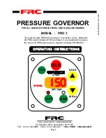
is extremely simple. The control module can be mounted any-
where on the pump panel.
PRO 3
control module has a square flange with an overall
dimensions of 4.25" X 4.25" . A cutout hole of 3.75" in diameter is required. To ensure
proper installation, follow the following procedures carefully:
1)
CONTROL MODULE
: Locate a suitable position on the pump panel and make sure
that check engine and stop engine indicators are closely mounted near
PRO 3
controller.
a)
Locate the center of the cutout hole and make a 3.75" diameter cutout.
b)
Insert the
PRO 3
controller into the cutout hole and locate the four 10-32 mount-
ing screw holes on the four corners of the flange.
c)
The dimensions for locating the cutout hole and the mounting screw holes can be
found in Figure 9.
2)
THROTTLE SERVO-MOTOR
Mark the point at which the servo-motor arm exits
the housing at idle and then when the engine is at max. The distance between these
points is the total motion of the actuator rod. The total motion of the actuator rod is
approximately 1 7/8" inches. The motion of the throttle arm at the slip fitting must be
slightly more than 1 7/8" to prevent breakage of the arm. If it is not, you have 2 choices:
i)
You may allow a little more clearance between the stop nuts and the slip fitting (1/
8" minimum is necessary to ensure correct engine idle). Doing that, however, may
delay the initial engine response somewhat.
Summary of Contents for GOVERNOR PRO 3
Page 19: ...servo p65 REV15AUG97 Page 19...


