background image

PHYSICAL INSTALLATION

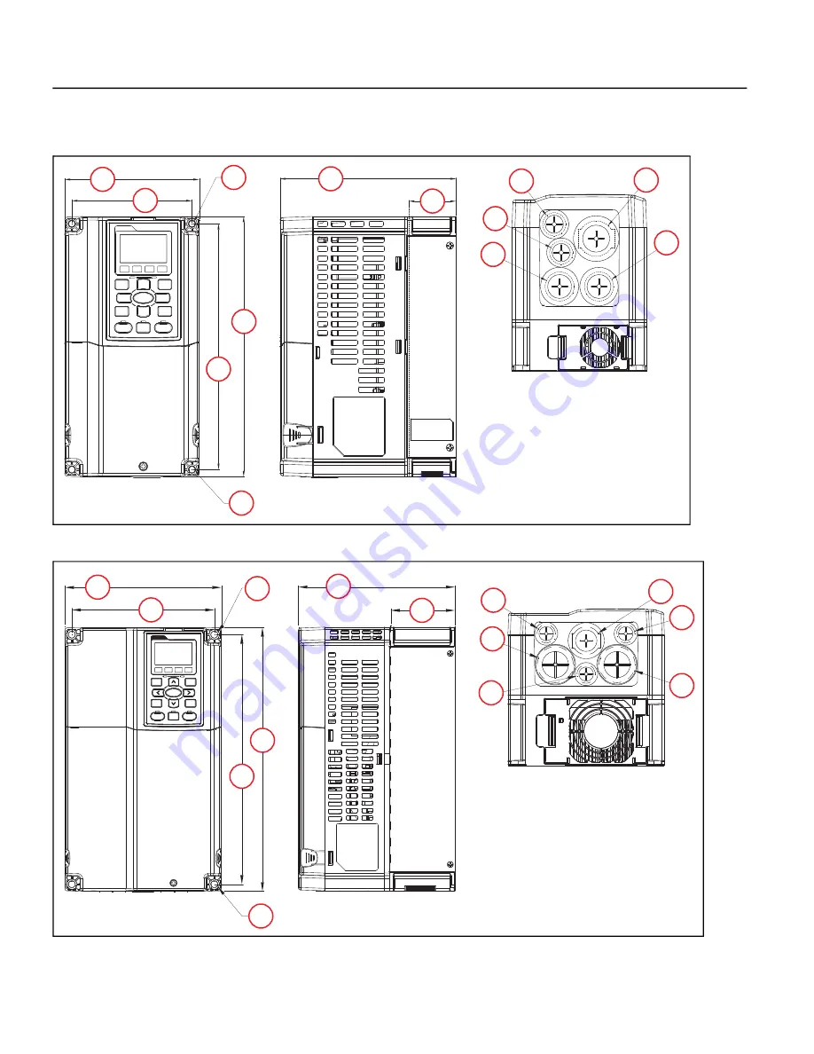
Drive Dimensions

28

Drive Dimensions

Frame A

Frame B

1

2

3

4

5

5

7

8

9

6

8

10

10

1 - 130 mm (5.12 in)
2 - 116 mm (4.57 in)
3 - 250 mm (9.84 in)
4 - 236 mm (9.29 in)
5 - 6.2 mm (0.24 in)

6 - 170 mm (6.69 in)
7 - 45.8 mm (1.8 in)
8 - 22.2 mm (0.87 in)
9 - 34 mm (1.34 in)
10 - 28 mm (1.10 in)

1

2

3

4

5

6

7

8

9

5

8

8

10

10

 1 - 190 mm (7.48 in)
 2 - 173 mm (6.81 in)
 3 - 320 mm (12.6 in)
 4 - 303 mm (11.9 in)
 5 - 8.5 mm (0.33 in)

6 - 190 mm (7.48 in)
 7 - 77.9 mm (3.07 in)
 8 - 22.2 mm (0.87 in)
 9 - 34 mm (1.34 in)
10 - 43.8 mm (1.72 in)

Summary of Contents for CERUS X-DRIVE CXD-003A-4V

Page 1: ...franklin electric com ENGLISH EN CERUSX DRIVE Installation and Operation Manual Firmware Version 1 2 ...

Page 2: ......

Page 3: ...CERUS X DRIVE INSTALLATION AND OPERATION MANUAL Firmware Version 1 2 Franklin Electric Co Inc ...

Page 4: ...nfringement of intellectual property rights or other violation of rights Franklin Electric does not warrant or make any representations regarding the use validity accuracy or reliability of the material in this publication Under no circumstances including but not limited to negligence shall Franklin Electric be liable for any direct indirect special inciden tal consequential or other damages inclu...

Page 5: ...uit Protection 36 Fuse and Circuit Breaker Sizing 36 Wire Sizing 38 Motor Cable Lengths for Submersible Pumping Applications 38 Suggested Maximum Motor Cable Lengths for Non Submersible Applications 38 Power Wiring Connections 39 Power Wiring Diagram 39 Control Circuit Connections 41 Terminal Identification 41 Example Configurations 43 4 20mA Speed Control Signal from an External BMS or PLC 43 0 1...

Page 6: ...ings Table Frequency Defaults with 50 Hz 62 INSTALLATION TESTING 63 Rotation Check 63 Feedback Checks 63 Performance Checks 63 Sleep Mode Check Pump Applications 64 OPERATION 65 Control Options 65 Hand Auto Controls 65 Forward or Reverse Selection 67 Jog Feature 67 Step Frequencies 68 Shutdown 68 Standard Operation with an Automated Control System 68 Standard Operation with PID Feedback Control 69...

Page 7: ...ection 94 Broken Pipe Protection for Pump Applications 95 Stall Prevention 95 ADVANCED APPLICATION OPTIONS 97 Operation with Permanent Magnet Motors 97 Setup FE MagForce Pump Motor 98 Basic Setup 98 Permanent Magnet Specific Parameters 98 Motor Specific Parameters 99 Autotune Characteristic Parameters 99 Tune motor control 99 Setup Non Franklin Electric PM Motors 99 Basic Setup 99 Permanent Magnet...

Page 8: ...reen 116 Support Screen 117 About Screen 117 Modbus Communication 117 X Drive Configuration for Modbus 117 Communication Parameters Setup 118 System Parameters Setup 118 ModBus Commands and Data Addresses 119 BACnet Communication 120 X Drive Configuration for BACnet 120 Communication Parameters Setup 120 System Parameters Setup 120 BACnet Device ID Setup 121 BACnet Objects 121 Commandable Analog V...

Page 9: ...scriptions Option Menu 227 Parameter Descriptions ADVANCE 2 Menu 229 Parameter Descriptions Motor Menu 232 SPECIFICATIONS 235 Common Specifications 235 200 230V Class 1 125HP 0 75 90kW 236 460V Class 1 75HP 5 5 55kW 237 460V Class 100 675HP 75 500kW 238 575 690V Class 1 150HP 1 5 175kW 239 575 690V Class 150 700HP 160 522kW 240 Derating Charts 241 Carrier Frequency Derating 241 230 V 460 V Inducti...

Page 10: ...f not avoided could result in death or serious injury Indicates a potentially hazardous situation which if not avoided could result in minor or moderate personal injury Indicates a potentially hazardous situation which if not avoided could result in damage to equipment or other property High voltages capable of causing severe injury or death by electrical shock are present in this unit To reduce r...

Page 11: ...matically after fault reset If required provide an emergency mechanical brake to prevent any hazardous conditions if VFD fails during oper ation Risk of damage to drive or other equipment Install and wire VFD according to the instructions in this manual Take protective measures against ESD Electrostatic Dis charge before touching control boards during inspection installation orrepair Do not connec...

Page 12: ...onal Extension Cards on page 125 Features Configuration Compatible with three phase induction or permanent magnet motors Extensive selection of models available Refer Models on page 13 Easy setup with built in application defaults Many programmable Input Output terminal options Available NEMA NEMA 1 or 3R and UL UL Type 1 IP21 or 4X enclosure offerings Application specific features Many pump speci...

Page 13: ...D 060A 4V CXD 073A 4V 45 0 60 0 73 0 22 5 30 0 36 5 575V CXD 003A 6V CXD 004A 6V CXD 006A 6V 3 0 4 3 6 7 1 5 2 1 3 3 CXD 009A 6V CXD 012A 6V CXD 018A 6VA CXD 024A 6V 9 9 12 1 18 7 24 2 4 9 6 0 9 3 12 1 CXD 030A 6V CXD 036A 6V CXD 045A 6V 30 0 36 0 45 0 15 0 18 0 22 5 Frame D Frame E Frame F 200V 230V CXD 146A 2V CXD 180A 2V 146 0 180 0 48 2 59 4 CXD 215A 2V CXD 276A 2V CXD 322A 2V 215 0 276 0 322 ...

Page 14: ...c VFD Configuration on page 18 Drive Configuration on page 47 and Operation on page 65 Submersible Pump Constant pressure Dew watering 2nd PID well recovery timer Pivot Irrigation Tank filling Long pipe dual acceleration Lead Lag Lead Lag Alternation Jockey Pony Dual demand Lubrication Line shaft turbine Refer to Basic VFD Configuration on page 18 Motor Cable Lengths for Submersible Pumping Applic...

Page 15: ...e shipping agent and your sales representative 2 Make sure the part number and product ratings on the identification label are correct for the applica tion 3 When possible remove the VFD cover and make sure the product ratings on the nameplate match the package label 4 The VFD comes in various forms of shipping crates If applicable remove the top and side fasteners from the packaging Risk of damag...

Page 16: ...ring the drive to the pallet 8 Inspect the VFD for damage 9 Allow the drive to remain on the pallet until you are ready to install it in the permanent location Refer to Mounting the Drive on page 20 Lifting When removing large VFDs from the pallet use suit able lifting equipment connected to the lifting holes at the top outer edges of the unit Use a spreader bar the same width as the drive so the ...

Page 17: ...ect Control Methods Install VFD Hardware Install Wiring Program Parameters Intended Function Air Handling Fluid Circulation Constant Pressure Pressure Boosting Irrigation Dewatering Carwashes Conveyors Crushers Grinders Hardware Application Supply Fan Exhaust Fan Cooling Tower Centrifugal Pump Submersible Pump Vacuum Pump Constant Torque FE Magforce Permanent Magnet Motor Automation Damper Control...

Page 18: ... power components can be damaged AC Line Reactor or Harmonic Filter A line reactor provides some degree of surge protection and decreases a level of harmonic distortion in the power line It is recommended when power source kVA rating is more than 10 times higher than VFD rating A Harmonic filter provides a higher level of harmonic mitigation Integrated DC Chokes are included in VFD models larger t...

Page 19: ...ronment If VFD will be installed in an envi ronment with a high probability of dust metallic particles mists corrosive gas or other contami nants the VFD must be mounted inside an appropriate electrical enclosure with proper NEMA UL Type or IP rating and adequate cooling When two or more VFDs are installed in a ventilated enclosure the cooling system should provide adequate airflow for all the VFD...

Page 20: ...he pallet use suitable lifting equipment connected to the lifting holes at the top outer edges of the drive 1 Use a spreader bar the same width as the drive so the lifting cables are straight up and down 2 Slowly lift the drive from the pallet 3 Use lifting equipment to place the drive in the desired installation location Risk of bodily injury or damage to drive or other equipment The drive should...

Page 21: ...lag screws for the bottom locations ensuring they are level and enter a solid stud or brace 2 Use a lifting device to lower the U shaped mounting slots onto the bottom lag screws The conduit box is not shown in this image to better show the bottom mounting slots 3 Hold the drive tight against the backing board and install the remaining two lag screws in the top mounting holes Mounting Frames F G a...

Page 22: ...er drive cover screws 2 Press the tabs on each side of the cover 3 Remove the cover 4 Remove five screws 5 Install the conduit box with five screws Tighten to a torque of 24 26 kg cm 20 8 22 6 Ib in 2 4 2 5 Nm 6 Replace the lower drive cover and rotate to the closed position Secure with two screws from step 1 Tighten to a torque of 12 15 kg cm 10 4 13 Ib in 1 2 1 5 Nm 1 2 2 3 4 4 5 5 ...

Page 23: ... 1 Loosen four lower drive cover screws 2 Remove the cover 3 Install the conduit box with six screws Tighten to a torque of 24 26 kg cm 20 8 22 6 Ib in 2 4 2 5 Nm 4 Replace the cover and secure with screws from step 1 Tighten to a torque of 12 15 kg cm 10 4 13 Ib in 1 2 1 5 Nm 2 1 3 ...

Page 24: ...ehind the flanges of the drive bottom 4 Secure the conduit box to the drive flange to flange with four screws Tighten the screws to a torque of 24 26 kg cm 20 8 22 6 Ib in 2 4 2 5 Nm 5 Install the conduit box cover using four screws from step 2 Tighten to a torque of 13 16 kg cm 20 8 22 6 Ib in 2 4 2 5 Nm 6 Replace the cover and secure with four screws from step 1 Tighten to a torque of 12 15 kg c...

Page 25: ... M5 Screw torque 24 26 kg cm 20 8 22 6 Ib in 2 4 2 5 Nm M8 Screw torque 100 120 kg cm 86 7 104 1 Ib in 9 8 11 8 Nm 5 Secure further with eight screws M5 Screw torque 24 26 kg cm 20 8 22 6 Ib in 2 4 2 5 Nm M8 Screw torque 100 120 kg cm 86 7 104 1 Ib in 9 8 11 8 Nm 6 Set the conduit box cover on the conduit box and slide it toward the conduit knockouts Tighten the screws to a torque of 24 26 kg cm 2...

Page 26: ...ion 1 Remove all screws hold ing the covers of the conduit box kit and remove the covers 2 Remove the screws shown from the bottom of the drive and remove the bracket 3 Fasten the M6 screws to two locations Tighten screws to a torque of 35 45 kg cm 30 3 39 Ib in 3 4 4 4 Nm 1 2 3 3 ...

Page 27: ...56 4 Ib in 5 4 6 4 Nm M8 Screws 7 9 and Nuts 14 17 100 110 kg cm 86 7 95 4 Ib in 9 8 10 8 Nm M10 Nuts 10 13 250 300 kg cm 216 9 260 3 Ib in 24 5 29 4 Nm 5 Replace the covers and screws removed in Step 1 to the original locations Tighten to a torque of 35 45 kg cm 30 3 39 Ib in 3 4 4 4 Nm 13 1 8 6 10 2 9 11 3 5 12 7 4 17 15 16 14 1 2 3 4 5 6 7 8 9 10 11 12 13 14 15 16 17 12 2 3 7 5 ...

Page 28: ...3 250 mm 9 84 in 4 236 mm 9 29 in 5 6 2 mm 0 24 in 6 170 mm 6 69 in 7 45 8 mm 1 8 in 8 22 2 mm 0 87 in 9 34 mm 1 34 in 10 28 mm 1 10 in 1 2 3 4 5 6 7 8 9 5 8 8 10 10 1 190 mm 7 48 in 2 173 mm 6 81 in 3 320 mm 12 6 in 4 303 mm 11 9 in 5 8 5 mm 0 33 in 6 190 mm 7 48 in 7 77 9 mm 3 07 in 8 22 2 mm 0 87 in 9 34 mm 1 34 in 10 43 8 mm 1 72 in ...

Page 29: ... 8 10 6 210 mm 8 27 inches 7 92 9 mm 3 66 inches 8 22 2 mm 0 87 inches 9 34 mm 1 34 inches 10 50 mm 1 97 inches 1 2 3 4 5 7 8 9 10 11 12 7 6 12 13 14 13 14 1 280 mm 11 in 2 235 mm 9 25 in 3 500 mm 19 7 in 4 475 mm 18 7 in 5 614 4 mm 24 2 in 6 442 mm 17 4 in 7 11 mm 0 43 in 8 255 mm 10 in 9 94 mm 3 7 in 10 16 mm 0 63 in 11 18 mm 0 71 in 12 62 7 mm 2 47 in 13 34 mm 1 34 in 14 22 mm 0 87 in ...

Page 30: ...14 13 14 13 8 275 mm 10 8 in 9 107 mm 4 22 in 10 16 mm 0 63 in 11 18 mm 0 71 in 12 76 2 mm 3 in 13 34 mm 1 34 in 14 22 mm 0 87 in 1 2 3 4 5 6 7 8 9 10 11 12 13 7 14 12 13 1 370 mm 14 6 in 2 335 mm 13 2 in 3 589 mm 23 2 in 4 560 mm 22 in 5 716 mm 28 2 in 6 528 mm 20 8 in 7 13 mm 0 51 in 8 300 mm 11 8 in 9 143 mm 5 63 in 10 18 mm 0 71 in 11 18 mm 0 71 in 12 92 mm 3 62 in 13 34 mm 1 34 in 14 22 mm 0 ...

Page 31: ...9 1 420 mm 16 5 in 2 380 mm 16 in 3 800 mm 31 5 in 4 770 mm 30 3 in 5 940 mm 37 in 6 717 mm 28 in 7 13 mm 0 51 in 25 mm 0 98 in 7 10 11 12 13 13 12 14 8 300 mm 11 8 in 9 124 mm 4 9 in 10 18 mm 0 71 in 11 18 mm 0 71 in 12 92 mm 3 62 in 13 35 mm 1 38 in 14 22 mm 0 87 in ...

Page 32: ...G 1 500 mm 19 7 in 2 440 mm 17 3 in 3 1000 mm 39 4 in 4 963 mm 38 in 5 1240 mm 49 in 6 914 mm 36 in 7 13 mm 0 51 in 26 5 mm 1 0 in 12 12 11 10 10 1 2 3 4 5 6 7 8 9 7 8 397 mm 15 6 in 9 27 mm 1 0 in 12 117 5 mm 4 6 in 13 34 mm 1 34 in 14 22 mm 0 87 in ...

Page 33: ...5 in 8 1403 mm 55 2 in 9 13 mm 0 51 in 26 5 mm 1 04 in 10 398 mm 15 7 in 11 45 mm 1 8 in 12 1701 mm 67 in 3 9 10 11 12 13 14 15 16 17 18 19 20 21 22 23 24 25 22 24 25 9 2 13 1347 mm 53 in 14 25 mm 1 in 15 500 mm 19 7 in 16 630 mm 24 8 in 17 760 mm 30 in 18 38 mm 1 5 in 19 65 mm 2 6 in 20 204 mm 8 in 21 68 mm 2 7 in 22 137 mm 5 4 in 23 117 5 mm 4 6 in 24 34 mm 1 3 in 25 22 mm 0 87 in ...

Page 34: ...42 5 mm 1 7 in 7 109 mm 4 3 in 8 404 mm 15 9 in 9 51 mm 2 in 10 13 mm 0 51 in 26 5 mm 1 04 in 1 2 3 4 5 6 7 8 9 7 10 11 12 13 14 15 16 17 18 10 16 20 20 21 19 21 11 25 mm 0 98 in 12 500 mm 19 7 in 13 630 mm 24 8 in 14 760 mm 30 in 15 68 mm 2 7 in 16 137 mm 5 4 in 17 103 mm 4 1 in 18 204 mm 8 in 19 117 5 mm 4 6 in 20 34 mm 1 3 in 21 22 mm 0 87 in ...

Page 35: ...VFD from transient power surges and provide some degree of harmonics distortion mitigation Power Wires Motor Wires ض ض ض ض ض Risk of damage to VFD or malfunction can occur Follow all wire routing and grounding instructions carefully Inductive currents caused by parallel wiring or close proximity between high voltage and control wiring can cause unexpected behaviors Do not run input power and motor...

Page 36: ...g See the table below for maximum current ratings of fuses and circuit breakers per NEC NOTE Follow local or regional regulations for specific requirements VFD Output Rating Short Circuit Rating Up to 50 HP 0 to 37 3 kW 5 000 Amperes rms 51 to 200 HP 39 to 149 kW 10 000 Amperes rms 201 to 400 HP 150 to 298 kW 18 000 Amperes rms 401 to 600 HP 299 to 447 kW 20 000 Amperes rms 601 to 900 HP 448 to 67...

Page 37: ...300 A 300 A CXD 220A 4V 167 A 220 A 400 A 400 A CXD 260A 4V 207 A 260 A 500 A 500 A CXD 310A 4V 240 A 310 A 600 A 600 A CXD 370A 4V 300 A 370 A 600 A 600 A CXD 460A 4V 380 A 460 A 800 A 800 A CXD 530A 4V 400 A 530 A 1000 A 1000 A CXD 616A 4V 494 A 616 A 1200 A 1200 A CXD 683A 4V 555 A 683 A 1350 A 1350 A CXD 770A 4V 625 A 770 A 1500 A 1500 A 575V 600V CXD 003A 6V 3 1 A 3 8 A 7 A 7 A CXD 004A 6V 4 ...

Page 38: ...100 ft 13 7 30 5 m Install output dV dt filter for a range 100 1000 ft 13 7 304 8 m or a sine wave filter for greater distances For submersible pumps install the output dV dt filter for 800 ft 243 8 m Motor Cable Lengths for Submersible Pumping Applications Refer to the Franklin Electric AIM Manual for wire gauge and distance information Suggested Maximum Motor Cable Lengths for Non Submersible Ap...

Page 39: ...ltage could result in death or serious injury Disconnect and lock out all power before installing or servicing equipment Always check if DC bus charge LED is off and DC voltage on the terminals DC 1 and DC is less than 30VDC before working on VFD wiring The DC bus capacitors may hold high voltage charge for several minutes after the VFD power is disconnected Connect the motor the drive metal plumb...

Page 40: ... lbs 3 43 Nm Frame C 1 0 AWG 69 4 in lbs 7 84 Nm Frame D0 2 0 AWG 69 4 in lbs 7 84 Nm Frame D 300 MCM or 4 0 AWG 156 in lbs 18 Nm Frame E 4 0 AWG 2 174 in lbs 20 Nm Frame F 300 MCM 2 or 4 0 AWG 2 156 in lbs 18 Nm Frame G Terminals R S T 250 MCM 4 156 in lbs 18 Nm Frame G Terminals U V T 500 MCM 2 354 in lbs 40 Nm Frame H 350 MCM 4 156 in lbs 18 Nm ...

Page 41: ...Sel IO 05 to match the switch setting Default 0 10 V AVI2 is a 0 10VDC input When an input source has been connected select the appropriate terminal in either Auto Speed Ref SET 07 Hand Speed Ref SET 09 or PID F B Source SET 18 AFM1 AFM2 are programmable multi function analog outputs Refer to AFMIOutSelect IO 59 and AFM2OutSelect IO 61 for options Each output can be set by micro switch to 0 10V mi...

Page 42: ...the 485 switch to the Down position to connect 120 Ω termination resistance for long distance or for an elec trically noisy environment 24 terminal provides 24 VDC with DCM common 50 mA power for digital control circuits and 150 mA for external transducers COM terminal is a digital inputs common By default it is connected by jumper to 24 to configure NPN Sink mode DCM is the internal 24 VDC power ...

Page 43: ...ect the transducer output Out wire to the ACI or AVI1 terminal The ACI micro switch should be in the up position If using the AVI1 terminal the AVI1 micro switch should be down Any shield wire should be connected to Earth ground ACIInputSel IO 00 or AVI1InputSel IO 05 should be set to the correct signal type Auto Speed Ref SET 07 should be set to PID Output PID F B Source SET 18 should be set to t...

Page 44: ...ansducer with VFD 24 VDC Power Connect the transducer positive Power wire to the VFD 24V terminal Connect the transducer output Out wire to the AVI1 AVI2 or ACI terminal The AVI1 micro switch should be in the up position If using the ACI terminal the ACI micro switch should be down Connect the transducer Com wire to the ACM terminal signal ground Use a jumper wire to connect the ACM and DCM termin...

Page 45: ... Connect the potentiometer Com wire to the ACM terminal signal ground Any shield wire should be connected to Earth ground ACI Input Sel IO 00 or AVI1 Input Sel IO 05 should be set to 0 10V Auto Speed Ref SET 07 or Hand Speed Ref SET 09 should be set to the chosen input Relay switching to control an external starter contactor or other system Connect the incoming power to the RC terminal Wire the co...

Page 46: ... be acti vated by internal power supply 3 Sink NPN mode with external 24VDC power source Remove any jumpers between 24 and COM or DCM and CM terminals Connect positive terminal of external power supply to COM terminal Connect dry contact or NPN transistor output from external control device to desired digital input and negative terminal of external power supply When contact is closed or transistor...

Page 47: ...ng mode and confirms changes to parameters The AUTO key places the VFD in Auto mode when keypad control is enabled The STOP RESET key stops the motor when keypad control is enabled or if enabled in remote mode The LED indicates that the VFD is stopped RESET can be used to clear some faults The FWD REV key selects motor direction when enabled The LED lights either green or red to indicate selection ...

Page 48: ...ttings Table SET Menu on page 50 for a list of automatically populated settings per application 1 VFD Max Freq VFD 00 The highest frequency speed allowable If running a FE MagForce pump this should be set to the calculated electrical frequency corresponding to the target pump RPM Refer to Setup FE MagForce Pump Motor on page 98 2 VFD Base Freq VFD 02 This should be set to the motor nameplate frequ...

Page 49: ...Hz Limit SET 23 Maximum PID frequency output will be limited to this value 18 Language Select a desired language for the display Press the MENU button and then press the BACK button Use the down key to scroll to 5_Set Language 19 Clock Current time and date This setting is used to record real time data for faults parameter changes etc To adjust press the MENU button and then press the BACK button ...

Page 50: ...nWC SET 20 PID F B Max 1 inWC 1 inWC 1 inWC 150 F 100 PSI 100 PSI 406 9 inWC 100 PSI 100 PSI 1 inWC SET 21 PID Set point 0 5 inWC 0 5 inWC 0 5 inWC 76 F 60 PSI 60 PSI 60 inWC 60 PSI 60 PSI 0 5 inWC SET 22 PID Lo Hz Limit 20 Hz 20 Hz 20 Hz 20 Hz 20 Hz 30 Hz 20 Hz 20 Hz 60 Hz 40 Hz SET 23 PID Hi Hz Limit 60 Hz 60 Hz 60 Hz 60 Hz 60 Hz 60 Hz 60 Hz 60 Hz 120 Hz 120 Hz SET 24 PID P Gain 1 1 1 1 2 2 1 1 ...

Page 51: ... PM Motor CODE Display Basic Supply Fan Exhaust Fan Cooling Tower Centrifugal Pump Submersible Pump Vacuum Pump Constant Torque FE MagForce PM Motor VFD 00 VFD Max Freq 60 Hz 60 Hz 60 Hz 60 Hz 60 Hz 60 Hz 60 Hz 60 Hz 120 Hz 120 Hz VFD 01 VFD Start Freq 0 50 Hz 0 50 Hz 0 50 Hz 0 50 Hz 0 50 Hz 0 50 Hz 0 50 Hz 0 50 Hz 0 50 Hz 0 50 Hz VFD 02 VFD Base Freq 60 Hz 60 Hz 60 Hz 60 Hz 60 Hz 60 Hz 60 Hz 60 H...

Page 52: ...t Dec 0 0 Hz 0 0 Hz 0 0 Hz 0 0 Hz 0 0 Hz 0 0 Hz 0 0 Hz 0 0 Hz 0 0 Hz 0 0 Hz VFD 45 Hopping Carrier Disable Disable Disable Disable Disable Disable Disable Disable Disable Disable VFD 46 ID Code Read Only Read Only Read Only Read Only Read Only Read Only Read Only Read Only Read Only Read Only VFD 47 VFD Rated Amps Read Only Read Only Read Only Read Only Read Only Read Only Read Only Read Only Read...

Page 53: ...Feet 3 Feet IO 19 Min Freq Limit 40 Hz 40 Hz 40 Hz 40 Hz 40 Hz 40 Hz 40 Hz 40 Hz 80 Hz 80 Hz IO 20 DI Filter 0 005 Sec 0 005 Sec 0 005 Sec 0 005 Sec 0 005 Sec 0 005 Sec 0 005 Sec 0 005 Sec 0 005 Sec 0 005 Sec IO 21 MI1 Define Speed L None None None None None None None None None IO 22 MI2 Define Speed M None None None None None None None None None IO 23 MI3 Define Speed H None None None None None N...

Page 54: ...nly Read Only Read Only Read Only Read Only Read Only Read Only Read Only Read Only IO 76 AI Loss Freq 40 Hz 40 Hz 40 Hz 40 Hz 40 Hz 40 Hz 40 Hz 40 Hz 80 Hz 80 Hz CODE Display Basic Supply Fan Exhaust Fan Cooling Tower Centrifugal Pump Submersible Pump Vacuum Pump Constant Torque FE MagForce PM Motor CODE Display Basic Supply Fan Exhaust Fan Cooling Tower Centrifugal Pump Submersible Pump Vacuum P...

Page 55: ...Disable Disable Disable Disable Disable ADV 49 J Start Press 0 5 inWC 0 5 inWC 0 5 inWC 75 F 54 PSI 54 PSI 54 inWC 54 PSI 54 PSI 0 5 inWC ADV 50 J Start Freq 50 Hz 50 Hz 50 Hz 50 Hz 50 Hz 50 Hz 50 Hz 50 Hz 100 Hz 100 Hz ADV 51 Main Stop Freq 40 Hz 40 Hz 40 Hz 40 Hz 40 Hz 40 Hz 40 Hz 40 Hz 80 Hz 80 Hz ADV 52 J Start Delay 20 Sec 20 Sec 20 Sec 20 Sec 20 Sec 20 Sec 20 Sec 20 Sec 20 Sec 20 Sec ADV 53 ...

Page 56: ...sabled Disabled Disabled PROT 20 PTC Level 50 50 50 50 50 50 50 50 50 50 PROT 21 OPO Trip Trip Coast Stop Trip Coast Stop Trip Coast Stop Trip Coast Stop Trip Coast Stop Trip Coast Stop Trip Coast Stop Trip Coast Stop Trip Coast Stop Trip Coast Stop PROT 22 OPO Delay 0 5 Sec 0 5 Sec 0 5 Sec 0 5 Sec 0 5 Sec 0 5 Sec 0 5 Sec 0 5 Sec 0 5 Sec 0 5 Sec PROT 23 OPO Current 1 1 1 1 1 1 1 1 1 1 PROT 24 OPO ...

Page 57: ...9 6 Kbps Comm 02 COM1 Loss Disable Disable Disable Disable Disable Disable Disable Disable Disable Disable Comm 03 COM1 Loss Delay 0 Sec 0 Sec 0 Sec 0 Sec 0 Sec 0 Sec 0 Sec 0 Sec 0 Sec 0 Sec Comm 04 COM1 Protocol 8 N 1 RTU 8 N 1 RTU 8 N 1 RTU 8 N 1 RTU 8 N 1 RTU 8 N 1 RTU 8 N 1 RTU 8 N 1 RTU 8 N 1 RTU 8 N 1 RTU Comm 05 Response Delay 2 ms 2 ms 2 ms 2 ms 2 ms 2 ms 2 ms 2 ms 2 ms 2 ms Comm 06 Main F...

Page 58: ...le Comm 53 MBus TCP Config None None None None None None None None None None Comm 54 MBus TCP Status 0 0 0 0 0 0 0 0 0 0 Comm 55 Set Comm Card 0 0 0 0 0 0 0 0 0 0 CODE Display Basic Supply Fan Exhaust Fan Cooling Tower Centrifugal Pump Submersible Pump Vacuum Pump Constant Torque FE MagForce PM Motor CODE Display Basic Supply Fan Exhaust Fan Cooling Tower Centrifugal Pump Submersible Pump Vacuum P...

Page 59: ...14 Relay exp RA18 None None None None None None None None None None Option 15 Relay exp RA19 None None None None None None None None None None Option 16 Relay exp RA20 None None None None None None None None None None Option 17 IO Card Type No Card No Card No Card No Card No Card No Card No Card No Card No Card No Card CODE Display Basic Supply Fan Exhaust Fan Cooling Tower Centrifugal Pump Submer...

Page 60: ...abled Disabled Disabled Disabled Disabled Disabled Disabled Disabled Disabled Disabled ADV2 47 Last Wake Time Read Only Read Only Read Only Read Only Read Only Read Only Read Only Read Only Read Only Read Only ADV2 48 H H Wake Time 4 Sec 4 Sec 4 Sec 4 Sec 4 Sec 4 Sec 4 Sec 4 Sec 4 Sec 4 Sec ADV2 49 H L Wake Time 10 Sec 10 Sec 10 Sec 10 Sec 10 Sec 10 Sec 10 Sec 10 Sec 10 Sec 10 Sec ADV2 50 L L Wake...

Page 61: ...r T 0 1 Sec 0 1 Sec 0 1 Sec 0 1 Sec 0 1 Sec 0 1 Sec 0 1 Sec 0 1 Sec 0 1 Sec 0 1 Sec Motor 17 Torque Cmp Gain 0 0 0 0 0 0 0 0 0 20 Motor 18 Slip Cmp Gain By VFD Rating By VFD Rating By VFD Rating By VFD Rating By VFD Rating By VFD Rating By VFD Rating By VFD Rating By VFD Rating By VFD Rating Motor 19 Slip Dev Level 0 0 0 0 0 0 0 0 0 0 Motor 20 Slip Dev Det T 1 Sec 1 Sec 1 Sec 1 Sec 1 Sec 1 Sec 1 S...

Page 62: ...z 20 Hz 20 Hz 60 Hz 40 Hz IO 52 FDT 2 Frequency 50 Hz 50 Hz 50 Hz 50 Hz 50 Hz 50 Hz 50 Hz 50 Hz 95 Hz 95 Hz IO 54 FDT 3 Frequency 50 Hz 50 Hz 50 Hz 50 Hz 50 Hz 50 Hz 50 Hz 50 Hz 95 Hz 95 Hz IO 57 FDT 4 5 Setting 3 Hz 3 Hz 3 Hz 3 Hz 3 Hz 3 Hz 3 Hz 3 Hz 3 Hz 3 Hz ADV 17 Mtr Switch Hz 50 Hz 50 Hz 50 Hz 50 Hz 50 Hz 50 Hz 50 Hz 50 Hz 95 Hz 95 Hz ADV 18 Lag Start Freq 49 5 Hz 49 5 Hz 49 5 Hz 49 5 Hz 49 ...

Page 63: ...or run current on the VFD display while running at full speed If it is higher than motor FLA or SFA check motor wiring and for any mechanical problems valves dampers etc that could create extra load on the motor shaft When running in PID mode check to see that transducer feedback i e pressure matches any gauges that may be installed If the target is not accurate verify that the transducer scaling ...

Page 64: ...and condition The system should be running at normal demand maintaining pressure setpoint then flow should be decreased slowly until stopped If the system does not enter Sleep mode it may be necessary to increase the PID Lo Hz Limit SET 22 to ensure that system pressure reaches PID Setpoint SET 21 plus boost if enabled If during normal operation the system enters Sleep mode but cycles on and off r...

Page 65: ...d Default The VFD Keypad HOA buttons including START and STOP are fully functional Digital Input Enables HOA control through an external switch wired to two digital inputs MI1 to MI8 These inputs should be set to 26_HOA Hand and 27_HOA Auto through parameters IO 21 to IO 28 HOA mode is then determined as follows RS485 Serial Enables HOA control through Modbus communications Com Card Enables HOA co...

Page 66: ...ut from external controller potentiometer or other device ACI Analog Input from external controller potentiometer or other device AVI2 Analog Input from external controller potentiometer or other device RS485 Serial Frequency input through Modbus control COM Card Frequency input through communications protocol PID Output VFD speed reference will be provided by PID control based on the difference b...

Page 67: ...nputs and another input should be set to 11_3 Wire Stop NOTE If MI10 input of IO expansion card is set to FWD MI11 will become REV input and MI12 is 3 Wire Stop input Load Rotation SET 15 This parameter controls whether a load can rotate in both directions or only one Jog Feature The Jog feature provides the ability to activate a motor momentarily The command can be executed using either the keypa...

Page 68: ...nal to one of the Digital Inputs MI1 MI8 and set the corresponding parameter to 36_Shutdown Latched Non Latching Mode IO 21 through IO 28 If a RUN command is present when the Shutdown signal is removed the VFD will restart based on HOA mode To enable this function connect the external emergency stop signal to one of the Digital Inputs MI1 MI8 and set the corresponding parameter to 35_Shutdown N La...

Page 69: ...ns verify or set the following parameters for PID operation Auto Speed Ref SET 07 Set to 7_PID Output Auto Run Command SET 08 Select source of Run Command either Keypad or external If using a Digital Input MI1 MI8 with a switch set the terminal to 38_FWD or 39_REV IO 21 28 PID Mode SET 17 Set to 1_PID Direct for most PID operations Feedback Source SET 18 Set to the terminal used for transducer con...

Page 70: ...ion Damper Mode IO 36 Enables or disables damper mode When enabled the damper relay is activated before every start including auto restarts Damper T Delay IO 37 Provides a run time delay without a damper limit switch or provides a Damper Fault delay for systems that include a damper limit switch The delay should be greater than damper open ing time Damper Output Terminal IO 47 through IO 49 Connec...

Page 71: ...nt to provide pressure boost 0 0 to 10 0 of PID F B Max SET 20 Default 3 Sleep Boost Timer SET 30 Timer that limits sleep boost duration if Sleep Boost setpoint is not reached 5 to 120 sec Default 10 sec Wakeup Level SET 31 Sets a wakeup level for VFD to quit Sleep mode and start running 0 0 to SET 21 Default 55 PSI Sleep Bump Timer SET 32 Sets a duration time for pressure bump to increase system ...

Page 72: ...rease at a rate of 0 5 Hz per second If system pressure is equal to or greater than 0 5 x SET 34 but less than 0 6 x SET 34 the frequency reference will stay at the current value If system pressure is equal to or greater than 0 6 x SET 34 but less than SET 34 setting the frequency reference will be decreased at a 0 5Hz per second rate However the rate will not be decreased below PID Low Hz Limit S...

Page 73: ...age show the difference between Lower and Higher trigger types Lower Used to refill water into a tank to maintain at ADV2 65 ADV2 66 When level becomes less than Trigger Level ADV2 65 the feature will be activated When the level is equal or greater than Trigger Level ADV2 65 Trigger Hysteresis ADV2 66 the function will be deactivated Higher Default Used to pump water from a tank to maintain ADV2 6...

Page 74: ...O 18 This parameter sets the minimum value of Aux Analog input corresponding to Min Freq Limit IO 19 If AUX input signal is below this value VFD will use IO 19 value as VFD or PID High Fre quency value Min Freq Limit IO 19 This parameter sets Minimum value for High Frequency Limiting range correspond ing to Min Limit Level IO 18 NOTE VFD will show Limit by Level message when High Freq Limit is dec...

Page 75: ...ed Recommended setting is 10 20 greater than ADV2 47 value Default 4 seconds H L Wake Time ADV2 49 This is an adjustable setting for High to Low Demand wake up time which should be determined during system startup Recommended setting is 20 30 greater than ADV2 47 value for proper Pipe Leak protection operation Default 10 seconds L L Wake Time ADV2 50 This is an adjustable setting for Low to Low De...

Page 76: ...s no timing If the VFD stops or trips the relay will deactivate Post Lube Tmr IO 45 This setting determines relay activation time after the VFD comes to a stop 0 Hz Screen Clean Relay When water is pumped from a lake or pond the suction screen requires periodic cleaning The VFD can automate this process by providing a relay output to an external solenoid valve that will discharge pressur ized wate...

Page 77: ... to desired interval in minutes for Clean Pump starts The timer will start at every VFD stop OCA Level PROT 07 and OCN Level PROT 08 Set to desired stall level for Anti Jam function Timers IMPORTANT If two or more timers are activated with different time settings the timer with the greater value will override other timers with a similar function Power On Run Delay This timer provides run delay at ...

Page 78: ...D stop when a run command is removed This timer is useful in vacuum pump pressure washer and similar applications Submersible motors should run for a minimum of one minute to dissipate heat build up from starting cur rent Set the following parameter to activate this feature Minimum Run ADV 34 Range 0 to 6000 seconds When set to 0 sec it is disabled When set to value greater than 0 and VFD is start...

Page 79: ... The timer output relay will be activated when Aux Timer input is activated and will be deactivated after timer expires no matter if input is active or not Changing input state during timer counting will not deactivate output relay On Pulser The timer output relay will be activated when Aux Timer input is activated and after timer expires it will be deactivated for duration of the timer Thus timer...

Page 80: ... speeds The VFD starts at the Standard rate and switches to Second ACC SET 54 and SecondDEC SET 55 when it reaches ACCChangeFreq SET 53 When the VFD decreases frequency below SET 53 SET 56 it will switch back to the Standard rates ACC Change Freq SET 53 Frequency to switch from Standard acceleration deceleration rate to second acceleration deceleration rate Second ACC SET 54 Time in seconds for dr...

Page 81: ...hole numbers one decimal place or two decimal places Aux Max Value ADV2 61 the maximum value of the auxiliary input can be set from zero to 30000 NOTE If using a PT100 or PTC for Aux AI set the maximum value to 200 C for PT100s and THIGH for PTCs Frequency Detection Trigger FDT The VFD can provide a selected relay output control by five different types of frequency detection triggers FDT1 through ...

Page 82: ...top VFD Run This selection activates start and stop commands in Auto mode If AutoRunCommand SET 08 is set to Digital Input with run command present or to 4_ExtHOAinAuto the VFD will start only when the VFD Run Program reaches On Time and it will stop when OFF Time is reached If during scheduled run HOA is changed to OFF or run command is removed VFD will stop During a scheduled event the VFD can r...

Page 83: ...ical values the program is disabled Program 1 Week Day s ADV 59 Selects which days of the week the Program will be effective For exam ple for 5 working days of the week set to _MTWTF_ and for weekends set to S_____S Program 2 Parameters Program 2 Setting ADV 60 Selects the type of event Program 2 will activate It has the same selections as Program 1 Setting ADV 56 Program 2 On Time ADV 61 Selects ...

Page 84: ... analog input or Comms every work day to preset Step Frequency 1 VFD 04 from 11 00 11AM to 17 00 5PM 3 Have the VFD change from No PID speed reference on Monday and Friday to Step Frequency 2 VFD 05 from 15 00 3PM to 19 00 7PM 1st Program Parameters Prog 1 Setting ADV 56 1_VFD Run Prog 1 On Time ADV 57 06 00 Prog 1 Off Time ADV 58 23 00 Prog 1 Week Day ADV 59 _MTWTF_ 2nd ProgramParameters Prog 2 S...

Page 85: ...AUTO mode the running frequency is displayed P PID Setpoint in application based units PSI inWC etc SET 21 This is adjustable using the keypad Use Line Display 1 SET 57 to permanently set the viewable parameter cycling the power of the drive or keypad to update the display User options include 0_Freq Command 1_Output Frequency 2_Multi Fn Display 3_Output Current 5 User Selectable Display Line 2 Di...

Page 86: ...er View Screen 2 This screen displays feedback from the analog inputs as a percentage View Screen 3 This screen displays the status of the multi function digital inputs in hex format Solid boxes indicate that the input is active View Screen 4 This screen displays the status of the multi function digital outputs in hex format Solid boxes indicate that the output is active FWD REV MI1 MI2 MI3 MI4 MI...

Page 87: ...t frequency Hz at the time The actual motor speed RPM at the time View Screen 7 This screen displays the following DC Bus voltage ripple DC Bus voltage ripple Output voltage View Screen 8 This screen displays the following Counter value Output power Ground fault View Screen 9 If an FE Connect Bluetooth communication card has been installed this screen displays the code for connecting with the mobi...

Page 88: ...riggered when the signal is either below 1_0 5xMin or at the transducer maximum value for the time set in ACI Loss Delay IO 03 ACI Loss Delay IO 03 Set the delay between signal loss detection and drive s response Default 1 0 sec AVI1 Signal Loss To enable Signal Loss for an AVI1 input adjust the following parameters AVI1 Input Selection IO 05 Make sure input is set to the transducer s signal type ...

Page 89: ...ther VFD features that use values as a percentage of the maximum feedback value F B Max will always use the main transducer s range To enable Transducer Redundancy adjust the following parameters PID F B Source SET 18 Selects the analog input terminal for PID Feedback source for the main pressure transducer Select ACI or AVI1 input ACI Input Selection IO 00 or AVI1 Input Selection IO 05 In the app...

Page 90: ...tered into PROT 33 it will refer to PROT 32 for VFD response PT100 L 1 Delay PROT 33 Enter the time delay between a high motor temperature detection and the VFD s response PT100 L 1 Freq PROT 32 Select the fall back level of the output frequency once a high temperature level PROT 30 is sensed for a predetermined length of time PROT 33 NOTE If the motor temperature falls below PT100 Level 1 PROT 30...

Page 91: ...culations to set analog input PTC curve parameters NOTE IDC RHIGH 10 V AFM1 DC Lvl ADV2 06 or AFM2 DC Lvl ADV2 07 In the appropriate parameter AFM1 or AFM2 set the maximum current for the sensor To determine the maximum current perform the following calculation IDC 0 020 A 100 IDC RHIGH 10 V 0 020 A is the high amperage from the analog output DIP switch setting 0 20 mA The calculation multiplies b...

Page 92: ...e at base frequency If all conditions are met VFD will trip above this level HLD Frequency SET 49 Set minimum frequency for HLD by Current or Torque detection HLD Delay SET 50 Range 0 to 360 seconds When timer expires if current or torque is still above limits and frequency is still above SET 49 VFD will trip based on SET 47 HLD Recovery Time SET 51 0 to 720 min default 0 min If timer is set to va...

Page 93: ...r fans It is not recommended for progressive cavity pumps or constant torque loads To enable Underload Protection adjust the following parameters Prime Time IO 39 Some pump applications require time for the pump to self prime before the load sta bilizes This setting adds a 0 to 6000 second delay before the VFD starts monitoring for Underload or No Flow conditions which protects against nuisance fa...

Page 94: ... run mini mum time before another ULD trip Overpressure The Overpressure feature stops the VFD when PID feedback exceeds a set value in either Hand or Auto To enable this feature adjust the following parameters OverPress Set SET 39 0_Disable 1_OP Trip or 2_OP Auto Reset When enabled if PID Feedback exceeds OverPress Level SET 40 the VFD trips on Overpressure fault 1_OP Trip Manual or remote reset ...

Page 95: ...evel SET 36 0 0 to PID F B Max SET 20 Setting of 0 0 disables the feature When pressure falls below this level and VFD continues to run above Broken Pipe Freq SET 37 Broken Pipe Delay SET 38 starts Broken Pipe Freq SET 37 PID Low Hz Limit SET 22 to PID Hi Hz Limit SET 23 Broken Pipe Delay SET 38 The timer provide a delay for triggering a Broken Pipe fault NOTE Manual or remote reset is required St...

Page 96: ...OPERATION Protection Features 96 ...

Page 97: ...compensation PM SVC operation has a sequence of three steps 1 DC Alignment A DC current and voltage is applied to the motor to align the rotor to the magnetic poles This alignment requires 3 seconds 2 I F Control A controlled current start of the motor is performed This technique provides higher starting torque than VF mode 3 Advance V F Control With the motor started frequency compensation stabil...

Page 98: ...orce application should only be used with Franklin Electric MagForce motors Do not use this selection with other permanent magnet motors 2 Input Phase SET 01 Verify that the setting matches the type of power supply Default 3 phase 3 Motor Horsepower SET 02 Enter the maximum rated horsepower from the motor nameplate 4 Motor FLA SFA SET 03 Set to the current rating on the nameplate associated with t...

Page 99: ...llow ing procedure Basic Setup IMPORTANT If the VFD has been used in a previous application the drive parameters should be completely reset using Parameter Reset ADV 03 option 4_Reset all Param 1 Application SET 00 Set to option 9_PMMotor This selection assumes the use of a 4 pole 3 phase PM motor running at 120 Hz and automatically updates relevant parameters to the proper defaults IMPORTANT Do n...

Page 100: ... to 3_PM Rotating or 4_PM No Rotation If a load is on the motor and can not be removed then a no rotation option should be selected Remove load from the motor to then use Rotating a An autotune no rotation will output high frequency into the motor to calculate the motor impedance values but not the Ke Coeff b An autotune with rotation will do same as no rotation and then turn the rotor of the moto...

Page 101: ...pensate for voltage drop on stator resistance at high motor loads in torque compensation function For PM motors max value is 5000 Setting this parameter to 0 will remove I F control and disable stability PM Bandwidth HS Motor 25 Allowable frequency bandwidth around desired frequency in order to adjust operating frequency to prevent vibrations in motor operation PMSVC Fltr Gain Motor 26 Gain value ...

Page 102: ...un if system pressure becomes 1 Equal to or greater than S Boost Value SET 29 jockey pump will stop 2 Less than Wakeup Level Wake Up Level SET 31 for two seconds the main pump will start and after J Start Delay ADV 52 system pressure is Below or at Setpoint and main VFD speed is greater than J Start Freq ADV 50 for two seconds jockey will continue to run helping main pump to maintain pressure setp...

Page 103: ...ecreased to reduce flow prevent cavitation and prolong pumping time The pump 1 dis charge pressure will drop and VFD2 will decrease its High Freq Limit and VFD3 etc will follow In this way all pumps will act the same without any communication between them To enable this feature set the following parameters AUX AI Select ADV2 58 Select the terminal AVI1 AVI2 ACI with the PID 2 transducer connection...

Page 104: ... reference from PID 2 back to PID 1 When running on PID 2 there are two parameters to switch back to PID 1 or stop VFD 1 PID2 Exit Level ADV2 44 If PID2 level reading becomes greater than this setting for 10 seconds VFD will switch speed reference from PID 2 back to PID 1 2 PID Stop Delay ADV2 43 If VFD has been running at PID2LowLimit ADV2 41 and cannot maintain the level setpoint for this time s...

Page 105: ...e this frequency it sets the first condition for starting a Lag pump Range Lag Stop Freq ADV 23 to PID Hi Hz Limit SET 23 Default 59 5 Hz Lag Start Delay ADV 19 Sets a delay time to start Lag pump when both frequency and pressure condi tions are met Default 10 sec Lag Start Level ADV 20 Sets a percentage of PID F B Max SET 20 to calculate MMC Below Setpoint as the second condition for starting a L...

Page 106: ...or ADV 27 time and then it will deactivate relay output to stop the first Lag Pump After a non adjustable 1 sec delay the VFD will change SET 22 to its original value and check for Lag Start Stop conditions If demand is still low the VFD will repeat Lag Stop sequence for additional Lag pumps If all Lag pumps are stopped the VFD will check for Sleep Mode conditions If the VFD run command is removed...

Page 107: ... primary units The X Drive system can support up to eight pumps and drives Method of Operation The communication between VFDs will provide Master Follower control and Lead Lag sequence switching which will allow pumps to alternate The pump system can be set with brown box VFDs separately enclosed VFDs or multiple VFDs enclosed in one industrial enclosure For complete redundancy each VFD requires a...

Page 108: ...s a Lead Assignment of the Lead drive can be assigned to other drives on a rotating basis IMPORTANT Since the Lead role can change each drive needs its own transducer or the system could have a single transducer with analog splitters to feed each drive Each drive needs to be set to the same setpoint If a change in setpoint is needed the setting needs to be updated on all the drives Lag A Lag drive...

Page 109: ...TMR ADV 46 In addition to balancing usage this practice would help ensure the proper functioning of Lag units that might otherwise be idle for extended periods The best practice would be to size and program all pumps drives the same Alternation Master Power Up For a system that is stopped and started on a periodic basis such as a man ufacturing plant it might be desirable to rotate system roles to...

Page 110: ...T 5 cables and RJ 45 ports or via shielded cables and VFD terminals SG and SG Wiring for communications should be from drive to drive in a chain as shown above The termination DIP switches should be ON up on both ends of the network The shield wires should be connected together and grounded on one end only Pressure Gauge Pressure Relief Valve Pressure Tank Pressure Transducer 2 4 230 200 150 100 5...

Page 111: ...nt SET 21 2 for the duration of VLag Stop Delay ADV 41 then Master will com mand Lag 1 drive to stop first start first stop If more Lag drives are running if conditions are met after Lag Run Timer the next Lag drive will be stopped VLag Stop Delay ADV 41 Sets delay time to stop Lag pump when both frequency and pressure Range 0 to 600 sec Default 5 sec VLead Lag ID ADV 42 Set this value to the init...

Page 112: ...ADVANCED APPLICATION OPTIONS Multi Drive Configurations 112 ...

Page 113: ...ssory X Drive FE Connect Bluetooth communi cation card in the VFD Refer to Optional Extension Cards on page 125 Setup Bluetooth Connection After installing the X Drive Connect app on your device use the following procedure to connect to a X Drive 1 From the Home screen tap Connect New Product 2 On the New Product Wizard screen tap either Scan QR Code Sticker or Enter the Bluetooth Key 3 If using t...

Page 114: ...g All Settings From here you will be able to program and verify all drive settings Refer to Setting Operating Param eters on page 48 Navigating the Mobile App My Products Screen 1 Menu Button takes user to Menu navigation screen Refer to Menu Screen on page 114 2 Listing of past drives which the app was connected 3 By selecting the drive s check box you can remove the drive from the list 4 Connect...

Page 115: ...atus and parameters in a pdf 3 All Settings provides listing of all parameters that can be individually be changed 4 Sync Date Time to update drive to match phone 5 Configuration Templates to create a file with all parameters of the drive which can be loaded onto another drive via current phone or shared to another phone Logs Screen The log screen shows a list of faults with a time date stamp 1 Sh...

Page 116: ...ew reports for current location 2 Generate New Reports creates reports with option of including Form 2207 for pumping applications NOTE This screen can be viewed when disconnected from the drive Documentation Screen 1 List of documents pertinent to product and commissioning 2 Franklin Tech Online Link to online video tutorial on Franklin Tech Online NOTE This screen can be viewed when disconnected...

Page 117: ...only 16 bit holding registers Addressing for the registers is partitioned into blocks that are multiples of 100 to group functionally similar data If the drive is configured to accept commands via remote communications it can be commanded to start stop run at a specified output frequency target a setpoint in PID control and reset faults For Modbus addresses refer to ModBus Commands and Data Addres...

Page 118: ...ing for communication timeout detection COM1 Protocol Comm 04 RS485 Protocol Data Bits Parity Stop Bits Message Format Response Delay Comm 05 Duration VFD waits before responding to received communication Main Frequency Comm 06 When Auto Speed Ref SET 07 is set to RS485 Interface the last frequency command is stored in this parameter After rebooting from an abnormal turn off or momentary power los...

Page 119: ...8 Reserved 8479 Decimal Portion of Output Current 8749 Reserved 8704 Output Current 8750 PID Reference Value 8705 Counter Value 8751 PID Offset Value 8706 Output Frequency 8752 PID Output Frequency 8707 DC Bus Voltage 8753 Hardware ID 8708 Output Voltage 8754 U phase Current 8709 Power Angle 8755 V phase Current 8710 Motor Power 8756 W phase Current 8711 Motor Speed 8759 Aux Analog Input 8712 Torq...

Page 120: ... is enabled Modbus communication and PLC communication are disabled on COM1 BACnet MAC ID Comm 24 This should be set to BACnet s MS TP station number Default 10 Range 0 to 127 BACnet Speed Comm 25 This should be set to the BACnet communication baud rate Default 38400 Range 9600 19200 38400 or 76800 bps Device ID Lo Comm 26 and Device ID Hi Comm 27 The combination of these two parameters is the Dev...

Page 121: ...AV 010 RW Reserved AV 011 through AV 026 RW Block Transfer Block transfer mapping 1 to 16 Dependent Object Number R W Object Name Object Description Unit AV 027 through AV 030 R Reserved AV 031 R Output Frequency Output Frequency Value Hz AV 032 through AV 034 R Reserved AV 035 R Output Torque Output Torque AV 036 through AV 038 R Reserved AV 039 R Status Word VFD Status Word from BV 16 through BV...

Page 122: ...n Status CPU Pins to Digital OUTs Status AV 068 R PLC D1043 Status PLC Register D1043 Status AV 070 R ULD Recover Counter SET 46 ULD Recover Counter Display AV 071 R HLD Recover Counter SET 52 HLD Recover Counter Display Object Number R W Object Name Object Description Unit Object Number R W Object Name Object Description BV 000 RW Freq Active CMD 0_Frq CMD 0Hz 1_Frq CMD FreqRefValue BV 001 RW FWD...

Page 123: ...Fault BV 024 R Signal Loss 0_ No Fault 1_ Signal Loss Fault BV 025 R Overpressure 0_ No Fault 1_ Overpressure Fault BV 026 R Damper Fault 0_ No Fault 1_ Damper Fault BV 027 R No Flow Fault 0_ No Fault 1_ No Flow Fault BV 028 R Fireman s Override 0_ Normal Mode 1_ Fireman s Override Mode BV 029 R Shutdown Mode 0_ Normal Mode 1_ Shutdown Mode BV 030 R Pipe Fill Mode 0_ Normal Mode 1_ Pipe Fill Mode ...

Page 124: ...COMMUNICATIONS BACnet Communication 124 ...

Page 125: ...Once configured the LED Indicators give the status of the network parameters and VFD power LED Light Status Indication Required Action NS Green red alternate Network self test mode None Solid green CIP connection established None Blinking green No CIP connection at power on None Solid red IP duplicate conflict Check IP Settings Blinking red COMMS loss Time out Check COMMS setting OFF No connection...

Page 126: ...and MO11 to the load Example PL pilot light on the diagram EMC 611A Extension AC Input Card This card adds six Digital Inputs MI10 MI15 with AC common terminal Neutral MI10 MI13 inputs functionality is programmable through parameters Option 00 to Option 05 Ratings are 100 130VAC 47 63Hz 27k impedance Response time for ON is 10ms and for OFF is 20ms EMC R6AA Extension Relay Card This card adds six ...

Page 127: ...t Contact with hazardous voltage could result in death or serious injury Disconnect and lock out all power before installing or servicing equipment Capacitors inside the drive can still hold lethal voltage even after power has been disconnected ALWAYS check if DC bus charge LED is off and DC voltage on the terminals DC 1 and DC is less than 30VDC before working on VFD wiring The DC bus capacitors ...

Page 128: ...ACCESSORIES Optional Extension Cards 128 Frame D Frame E Frame F ...

Page 129: ...ACCESSORIES Optional Extension Cards 129 Frame G Frame H ...

Page 130: ...Not currently used 5 Align holes in card over the positioning pins 6 Press down on the card until retaining clips snap into place 7 When clips are secure install retaining screws and tighten to a torque of 6 8 kg cm 5 2 7 Ib in 59 79 Nm Once an extension card has been installed it must be activated to be recognized by the system The activation procedure differs depending on the type of card For mo...

Page 131: ... and automatically change Comm 30 to 5_Ethernet IP 2 Download card values to the drive Set MBusCardReset Comm 52 to 1_Enable This populates default values from the card into the appro priate drive parameters For example IP Address 192 168 1 5 to Comm 38 to Comm 41 Address Mask 255 255 255 0 to Comm 42 to Comm 45 Gateway Address 192 168 1 1 to Comm 46 to Comm 49 NOTE When complete Comm 52 will auto...

Page 132: ...ACCESSORIES Optional Extension Cards 132 ...

Page 133: ...ACK or DOWN or FAULT Using the displayed fault title refer to the following table for troubleshooting details Diagnostic Fault Codes Fault Display Description ACE 48 ACI loss Analog current input loss including all 4 20 mA and 2 10V signals Action level When the analog input is below ACI Loss Level IO 02 only detects 4 20 mA and 2 V inputs Action time After ACI Loss Delay IO 03 Related parameters ...

Page 134: ... at startup after Anti jam operation Related parameters ADV2 55 selects Anti jam operation Reset method Manually Reset condition Fault Warning is determined by ADV2 55 Recorded Yes Possible Causes Corrective Action Impeller or pump is clogged with debris Load is larger than motor Bad motor Remove debris impeller pump Replace and resize motor Attempt to start motor without impeller pump If problem ...

Page 135: ...speed is above frequency setting Action time After Broken Pipe Dly SET 38 Related parameters Broken Pipe Level SET 36 Broken Pipe Freq SET 37 Broken Pipe Delay SET 38 Reset method Manually Reset condition Immediately after piping has been repaired Recorded Yes Possible Causes Corrective Action Pipe broken or hole in tubing between pump and sensor Pump sized too small Parameters set incorrectly Che...

Page 136: ...led CANopen speed incorrect EMI Interference Communication cable broken Firmware update Check Comm card installation Check communications settings Check wiring and grounding for possible interference Make sure communication circuit is wired in series For CFrE error reset parameters and station address Fault Display Description cd1 33 Ias sensor Err U phase current detection error when power is ON ...

Page 137: ...nication circuit It is recommended to separate the communication circuit from the main circuit or wire in 90 degree for effective anti interference performance Check if the setting for Comm 02 is the same as the setting for the master unit Check the cable and replace it if necessary Fault Display Description CE10 58 PC time out Modbus transmission time out occurs Action and Reset Action level When...

Page 138: ...en CANopen Node Guarding detects that one of the followers does not respond Action time Time set by upper unit Reset method Manually Reset condition The upper unit sends a reset package to clear the fault Recorded Yes Possible Causes Corrective Action Guarding time is too short EMI Interference Faulting communication cable Increase guarding time and detection times Verify wiring and grounding of c...

Page 139: ... frequency is 0 Hz Reset condition Stable power is restored Recorded Yes Possible Causes Corrective Action Unstable power source Power is off Other large loads in power system Check power supply capacity Separate other large loads Fault Display Description DPR 177 Damper Fault Motor does not start because of damper error Action and Reset Action level Damper limit switch has not closed in time to s...

Page 140: ... function set to external fault Check Normally Open Normally Closed settings for DI NO NC IO 46 Fault Display Description EF1 50 Emergency stop Drive has been stopped through an external switch Action and Reset Action level When a multi function input terminal MI1 to MI8 is set to emergency stop and the contact is closed the AC motor drive stops output and the motor coasts to stop Action time Imme...

Page 141: ...otor Remove the shaft lock Reduce the load and increase the motor capacity Adjust settings for V F curve especially the setting value for the mid point voltage if the mid point voltage is set too low the load capacity decreases at low speed Decrease low speed operation time Replace the drive with a dedicated to VFD model Increase the motor capacity PROT 16 1 electronic thermal relay selection moto...

Page 142: ...n of FO Retry Delay IO 32 Recorded Yes Possible Causes Corrective Action A secondary fault is present Too many faults during FO Retry Delay FO mode initiated prematurely causing secondary fault View fault log to identify active fault Review fault log to diagnosis system issues Review FO mode setup including digital input assignments Fault Display Description FStp 90 Force Stop Keypad forces PLC to...

Page 143: ...Description Hd0 36 cc HW error Current clamp hardware protection Action and Reset Action level Hardware detection Action time Immediately Reset method Cycle the power Recorded Yes Possible Causes Corrective Action Hardware failure If condition still exists after power restart please call Technical Support Fault Display Description Hd1 37 oc HW error oc hardware protection error when power is ON Ac...

Page 144: ...ction on page 92 Reset condition Correct overloading condition Recorded Yes Possible Causes Corrective Action Motor and or pump misalignment Dragging motor and or pump Motor and or pump locked Abrasives in pump Excess motor cable length Amperage is above MAX AMPS at minimum frequency Remove and repair or replace as required Reduce motor cable length Adhere to Maximum Motor Cable Length table For F...

Page 145: ...us voltage is lower than LV Level PROT 03 during deceleration Action time Immediately Related parameters PROT 03 LV Level Reset method Manually or Automatically if in Auto mode and Auto Restart is enabled Reset condition Reset when DC bus voltage is higher than PROT 03 30 V Frame A D 40 V Frame E and below Recorded Yes Fault Display Description Lvn 13 Lv at normal SPD DC bus low voltage at constan...

Page 146: ... Fault Display Description MVWS 183 M VFD Wrong Set Wrong settings of Multi VFD Settings of follower this drive is different from the master Action and Reset Action level ADV 35 ADV 36 SET 07 and SET 17 different than master drive To identify master drive set SET 58 to 23_Commu Role On screen 0 No Role 1 Master and 2 Follower Action time Immediately Related parameters ADV 35 ADV 36 SET 07 SET 17 R...

Page 147: ...vement of fluid Action and Reset Action level Multi function Input set to No Flow function is activated Detection occurs after motor runs above min frequency for duration of Prime Time IO 39 and above No Flow Freq IO 40 No Flow Mode IO 38 sets operation as 1_Trip or 2_Sleep where additional condition of No Flow IO 38 has to be met to incur sleep mode Action time Once detection occurs MI has to be ...

Page 148: ...of the short circuits or replace the cable before turn ing on the power Check the motor insulation value with megger Replace the motor if the insulation is poor Check if the output current during the whole working process exceeds the AC motor drive s rated current If yes replace the AC motor drive with a larger capacity model Reduce the load or increase the capacity of AC motor drive Check the mot...

Page 149: ... deceleration time of S curve Set auto acceleration and auto deceleration parameter ADV 06 Set over current stall prevention function PROT 07 Replace the drive with a larger capacity model Check the action timing of the mechanical brake Check the motor cable and remove causes of the short circuits or replace the cable before turn ing on the power Check the motor insulation value with megger Replac...

Page 150: ...s and frequency voltage When the fault occurs and the frequency voltage is too high reduce the voltage Adjust over torque offset value refer to MOTOR 17 for torque compensation gain until the output current is reduced and not motor stall Adjust the torque compensation refer to MOTOR 17 for torque compensation gain until the output current reduces and the motor does not stall Verify the wiring of t...

Page 151: ...t sink is not obstructed Check if the fan is operating Check if there is enough ventilation clearance for the drive Reduce load Replace drive with a larger capacity model Remove from direct sunlight Fault Display Description oH2 17 Heat Sink oH Capacitance temperature causes heatsink overheating Action and Reset Action level Temperature error level depends on VFD model Action time 100 ms Reset met...

Page 152: ...lly Replace the fan Decrease low speed operation time Replace the motor with a dedicated to VFD model Increase the motor capacity Increase the setting values for accel decel time Adjust settings for V F curve especially the setting value for the mid point voltage if the mid point voltage is set too low the load capacity decreases at low speed Reset to the correct motor rated current Check the conn...

Page 153: ...cked Abrasives in pump Excess motor cable length Amperage is above MAX AMPS at minimum frequency Remove and repair or replace as required Reduce motor cable length Adhere to Maximum Motor Cable Length table For FE MagForce application verify motor model selection pump load and max amps Fault Display Description oL3 87 Derating Error Overload protection at low frequency with high current Action and...

Page 154: ... that the three phase current is balanced via a current clamp meter If it is balanced and the OPHL fault still exists call Technical Support Make sure the capacity of the drive and motor match to each other Fault Display Description OPRS 174 Overpressure M System exceeds pressure limit Action and Reset Action level PID Feedback is greater than OverPress Level SET 40 Operation set by OverPress Set ...

Page 155: ...torque described in the user manual Wire correctly Replace the cut off cable Verify the setting value for IPO Check Time PROT 26 and IPO Ripple PROT 27 Check the power three phase status Fault Display Description oSL 63 Over slip error On the basis of the maximum slip limit set via MOTOR 19 the speed deviation is abnormal When the motor drive out puts at constant speed F H or F H exceeds the level...

Page 156: ...ith a larger capacity model The setting for stall prevention level should be larger than no load current Check if the input voltage is within the rated AC motor drive input voltage range and check for possible voltage spikes If the phase in capacitor or active power supply unit acts in the same power system the input voltage may surge abnormally in a short time In this case install an AC reactor U...

Page 157: ...ce Increase the setting value of SET 12 VFD 22 VFD 24 and SET 55 deceleration time Connect brake resistor brake unit or DC bus on the drive Reduce the brake frequency Replace the drive with a larger capacity model Use S curve acceleration deceleration Use over voltage stall prevention PROT 04 Use auto acceleration and auto deceleration ADV 06 Adjust braking level VFD 37 or the bolt position of the...

Page 158: ...istor or brake unit Malfunction caused by interference Connect brake resistor brake unit or DC bus to the drive Reduce the load Replace to drive with a larger capacity model Adjust braking level VFD 37 or bolt position of the brake unit The setting of stall prevention level should be larger than no load current Use over voltage stall prevention function PROT 04 Use a brake unit or DC bus Check if ...

Page 159: ... internal terminals Troubleshoot the ground fault Fault Display Description Pcod 52 Password error Entering the wrong password three consecutive times Action and Reset Action level Entering the wrong password three consecutive times Action time Immediately Reset method Manually Reset condition Power off Recorded Yes Possible Causes Corrective Action Incorrect password input through ADV 02 Input th...

Page 160: ...eration Check if the three phase input power is normal Verify the wiring grounding of the main circuit to prevent interference Cycle the power after checking the power If ryF error still exists call Technical support Fault Display Description S1 73 S1 emergy stop Emergency stop for external safety Action and Reset Action level Hardware detection Action time Immediately Reset method Manually Reset ...

Page 161: ...vating shutdown Nuisance tripping External shutdown switch is Normally Closed circuit no shutdown with switch closed Reset external device causing shutdown Adjust DI filter IO 20 Set MI to NC with DI NO NC IO 46 Fault Display Description STL1 72 STO Loss 1 STL2 77 STO Loss 2 STL3 78 STO Loss 3 Safe Torque Off Loss 1 STO1 SCM1 internal loop detection error Safe Torque Off Loss 2 STO2 SCM2 internal ...

Page 162: ...Causes Corrective Action Hardware failure Wait for 10 minutes and then cycle the power If fault still exists call Technical Support Fault Display Description TPAI 182 Trip by AI Analog Input or PID Feedback has exceeded threshold Action and Reset Action level Trigger Source ADV2 63 reach threshold set by ADV2 64 through ADV2 66 Action time Immediately Related parameters ADV2 62 through ADV2 66 Res...

Page 163: ...uses Corrective Action Over pumped well Broken shaft or coupling Blocked screen worn pump Air gas locked pump X Drive not set properly for pump end Underload Sensitivity setting incorrect Frequency near maximum with load less than ULD Level SET 42 System is drawing down to pump inlet out of water High static light loading pump reset ULD Level SET 42 if not out of water Check pump rotation reconnec...

Page 164: ...y Description ApDx 127 App Disconnected App disconnected from X Drive Action and Reset Action condition Software check Action time Immediately Reset method Automatically Reset condition Wait 3 seconds Recorded N A Possible Causes Corrective Action App has disconnected from VFD Phone is out of range from VFD Phone stopped transmitting Bluetooth Open app and reselect VFD from My Products page Move p...

Page 165: ...d CAN_L communication cable is short the master receives wrong package and CbFn fault occurs Action time Immediately displays when the fault is detected Reset method Manually Reset condition Cycle the power Recorded When SET 08 does not equal 3 CbFn is a warning and isn t recorded Possible Causes Corrective Action Check if the CANopen card is installed Check if the CANopen speed is correct Malfunc...

Page 166: ...ircuit or wire in 90 degree for effective anti interference performance Check if the setting for Comm 02 is the same as the setting for the upper unit Check the cable and replace it if necessary Warning Display Description CE10 5 Comm Error 10 RS 485 Modbus transmission time out Action and Reset Action condition CE10 When Comm 10 0 and the motor drive keeps running and the time has exceeded Comm 0...

Page 167: ... times Verify the wiring and grounding of the communication circuit It is recommended to separate the communication circuit from the main circuit or wire in 90 degree for effective anti interference performance Make sure the communication circuit is wired in series Use CANopen cable or add terminating resistance Warning Display Description CHbn 37 Heartbeat T out CANopen heartbeat error Action and...

Page 168: ...set condition Directly resets Recorded N A Possible Causes Corrective Action When copy PLC mode and the process is incorrect Cycle the power and copy PLC mode again Warning Display Description CPLF 95 Copy PLC Func KPC CC01 Copy PLC function should be executed when PLC is off Action and Reset Action condition Software detection Action time Immediately Reset method Manually Reset condition Directly...

Page 169: ...cess Warning Display Description CPLv 93 Copy PLC Version Copy PLC version error Action and Reset Action condition Software detection Action time Immediately Reset method Manually Reset condition Directly resets Recorded N A Possible Causes Corrective Action Incompatible PLC program is copied to the drive Check if the copied PLC program is for the X Drive Use the correct PLC program Warning Displa...

Page 170: ...diately displays when the fault is detected Reset method Automatically Reset condition When the master resends a SDO command and receives the response the warning clears Recorded N A Possible Causes Corrective Action Warning Display Description dAvE 18 Deviation Warn Over speed deviation warning Action and Reset Action condition N A Action time N A Reset method Automatically Reset condition After ...

Page 171: ...voltage drop Unexpected power off Check the power consumption Warning Display Description EC3F 87 ExCom Mail fail Mail warning Alarm mail will be sent when the communication card establishes alarm conditions Action and Reset Action condition Communication card establishes alarm conditions Action time Immediately Reset method Manually Reset condition Immediately Recorded N A Possible Causes Correct...

Page 172: ... Reset method Automatically Reset condition After communication card is re installed Recorded N A Possible Causes Corrective Action Warning Display Description ECCFF 75 ExCom Facty def Factory default setting error Action and Reset Action condition Factory default setting error Action time Immediately Reset method Cycle the power Reset condition N A Recorded N A Possible Causes Corrective Action F...

Page 173: ...dition N A Recorded N A Possible Causes Corrective Action The setting address exceeds the range 0 63 The speed setting exceeds the range The address is duplicated with other nodes on the BUS Check the address setting of the communication card Comm 34 Standard 0 2 Non standard 0 7 Reset the address Warning Display Description ECiF 76 ExCom Inner err Serious internal error Action and Reset Action co...

Page 174: ...es Corrective Action IP conflict DHCP IP configuration error Reset IP MIS check if DHCP Server works normally Warning Display Description ECLv 71 ExCom pwr loss Low voltage of communication card Action and Reset Action condition The 5V power that drive provides to communication card is to low Action time Immediately Reset method Re power Reset condition N A Recorded N A Possible Causes Corrective ...

Page 175: ...dware detection Action time Immediately Reset method Manually Reset condition Immediately Recorded N A Possible Causes Corrective Action The Master communication value is more than the allowable quantity of the communication card The upper unit is online without communicating and does not break off the Modbus TCP link causes occupy connection A new Modbus TCP connection is built every time when th...

Page 176: ...value Revise program of upper unit the communication should be break off when it is not used for a long time Revise program of upper unit use the same Modbus TCP connection when connected to the same communication card Warning Display Description ECPi 79 ExCom Conf data Profibus configuration data error Action and Reset Action condition N A Action time N A Reset method Manually Reset condition Imm...

Page 177: ...tion time N A Reset method Automatically Reset condition CMC EC01 resets when the communication with the upper unit is back to normal Recorded N A Possible Causes Corrective Action Communication card is not connected with the upper unit Communication error of the upper unit Check if the connection of the communication cable is correct Check if the communication of the upper unit is normal Warning ...

Page 178: ... frequency ramps down linearly when Aux AI is between Max Limit Level IO 17 and Min Limit Level IO 18 where Min Freq Limit IO 19 corresponds with Min Limit Level IO 18 Action time Immediately Related parameters IO 16 through IO 19 Reset method Automatically Reset condition Increase Aux AI above Max Limit Level IO 17 Recorded N A Possible Causes Corrective Action Aux AI signal is changing Max Freq ...

Page 179: ...Remove the obstruction or replace the cooling fan Increase ventilation space of the drive Decrease loading Decrease the carrier Replace with a drive with larger capacity Replace with a drive with larger capacity Warning Display Description oH2 10 Over heat 2 Warn The drive has detected over heat of the board level component Action and Reset Action condition oH2 error level minus 5 C Action time Th...

Page 180: ...method Automatically Reset condition When output current PROT 13 5 the Ot2 warning clears Recorded N A Possible Causes Corrective Action Incorrect parameter setting Mechanical error e g mechanical lock due to over torque The load is too large Accel Decel time and working cycle is too short V F voltage is too high The motor capacity is too small Over load during low speed operation The torque compe...

Page 181: ...th a current clamp meter If the current is balanced and the OPHL error still shows on the display return to the factory for repair Choose the matches capacity of the drive and motor Warning Display Description oSL 24 Over Slip Warn Over slip warning By using the maximum slip as the base when the drive outputs at constant speed and the F H or F H exceeds Motor 19 level and Motor 20 setting time 100...

Page 182: ...e Action Incorrect parameter setting Mechanical error e g mechanical lock due to over torque The load is too large Accel Decel time and working cycle is too short V F voltage is too high The motor capacity is too small Over load during low speed operation The torque compensation is too large Improper parameter settings for the speed tracking function including restart after momentary power loss an...

Page 183: ...fault is detected Reset method Cycle the power Reset condition N A Recorded N A Possible Causes Corrective Action Malfunction caused by interference Communication cable is broken or bad connected For interference Verify wiring grounding of the communication circuit It is recommended to separate the com munication circuit from the main circuit or wire in 90 degree for effective anti interference pe...

Page 184: ...en Master node error Action and Reset Action condition When the CANopen master configures different setting nodes from the actual nodes the PCnL warning displays Action time Immediately displays when the fault is detected Reset method Automatically Reset condition When connect BUS to the original follower or change the configured node numbers to meet the actual node quantity the warning clears Rec...

Page 185: ...s that there is interference or the command from the upper unit does not meet the CANopen command format Action and Reset Action condition N A Action time Immediately displays when the fault is detected Reset method Automatically Reset condition The warning clears after receives another normal packet Recorded N A Possible Causes Corrective Action Malfunction caused by interference The command from...

Page 186: ...en PID enables Action and Reset Action condition When the analog input is lower than 4 mA only detects analog input of 4 20 mA Action time N A Reset method Automatically Reset condition Immediately reset Recorded Yes Possible Causes Corrective Action Loose or broken PID feedback wiring Feedback device malfunction Hardware error Tighten the terminals again Replace with a new cable Replace with a ne...

Page 187: ...thod Automatically Reset condition Check if the program is correct and re download the program If the fault does not exist the warning clears Recorded N A Possible Causes Corrective Action During PLC operation the external Modbus has written read incorrect data to internal PLC program Check if the upper unit transmits the correct command Warning Display Description PLdF 59 Download fail PLC downlo...

Page 188: ...ically Reset condition Check if the program is correct and re download the program If the fault does not exist the warning clears Recorded N A Possible Causes Corrective Action The PLC runs an incorrect command during operation Unsupported command has used while downloading the program When starting the PLC function and there is no program in the PLC the PLFF warning shows This is a normal warning...

Page 189: ...mediately Reset method Automatically or Manually Reset condition Cycle the power Recorded N A Possible Causes Corrective Action When using RTC function for PLC program and the drive is power off over 7 days or KPC CC01 does not connect to the drive for a long time the RTC time is different with the internal calculated time when re connect the keypad to the drive KPC CC01 does not adjust the RTC ti...

Page 190: ...fault is detected Reset method Automatically Reset condition Check if the program is correct and re download the program If the fault does not exist the warning clears Recorded N A Possible Causes Corrective Action The program detects checksum error during PLC operation Disable PLC Remove PLC program ADV 03 6 Enable PLC Re download PLC program Warning Display Description PLSv 51 Save mem defect Da...

Page 191: ...ith added parameters to the drive with old firmware version Action time N A Reset method Manually Reset condition Immediately Recorded N A Possible Causes Corrective Action Add new parameters to the new firmware version Malfunction caused by interference SE2 In this stage the copied data has been transmitted to the Follower The Follower compares and processes the copied data and then saves the dat...

Page 192: ...tion When running Motor 00 motor parameter auto tuning Action time N A Reset method Automatically Reset condition When auto tuning is finished and no error occurs Recorded N A Possible Causes Corrective Action The motor parameter is running auto tuning When the auto tuning is finished the warning automatically clears Warning Display Description uC 13 Under Current Low current Action and Reset Acti...

Page 193: ... drive Action and Reset Action condition The number of drives detected are less than Multi VFD Set ADV 35 This warning only occurs on the master drive To identify master drive set SET 58 to 23_Commu Role then 0 No Role 1 Master and 2 Follower Action time Immediately Related parameters ADV 35 ADV 36 and ADV 37 Reset method Automatically once parameters are set correctly Reset condition Immediately ...

Page 194: ... slide out the fan 2 Disconnect the power connector before completely removing the fan Risk of bodily injury or damage to drive or other equipment Contact with hazardous voltage could result in death or serious injury Disconnect and lock out all power before installing or servicing equipment Do not attempt to replace fans until power has been removed and 10 minutes have passed to allow internal vo...

Page 195: ...Sink Fan Some Frame C models use one fan and some use two 1 Before removing fans remove the cover using a flathead screwdriver 2 Disconnect fan power connectors 3 Remove screws and remove fans When replacing screws tighten to a torque of 8 67 to 10 4 in lbs 0 98 to 1 18 Nm 4 When installing new fans make sure label faces the inside of the drive 1 2 1 2 3 ...

Page 196: ... press the tabs on both sides to remove the lower cover When replacing screws tighten to a torque of 10 4 to 13 in lbs 1 18 to 1 47 Nm 2 Press the top of the keypad and remove the keypad 3 Remove two screws and press the tabs on both sides to remove the upper cover When replacing screws tighten to a torque of 5 2 to 6 9 in lbs 0 59 to 0 78 Nm 4 Disconnect fan power connector 5 Remove one screw and...

Page 197: ...the fan assembly When replacing screws tighten to a torque of 20 8 to 22 1 in lbs 2 35 to 2 5 Nm 2 Disconnect the power connectors before completely removing the fan Frame E Capacitor Fan 1 Remove four screws to release and slide out the fan assembly When replacing screws tighten to a torque of 20 8 to 22 1 in lbs 2 35 to 2 5 Nm 2 Disconnect the power connectors before completely removing the fan ...

Page 198: ...g the fan Frame F Capacitor Fan 1 Remove four screws and remove the lower cover When replacing screws tighten to a torque of 10 4 to 13 in lbs 1 18 to 1 47 Nm 2 Remove four screws and remove the upper cover When replacing screws tighten to a torque of 20 8 to 22 1 in lbs 2 35 to 2 5 Nm 3 Disconnect fan power connector and remove three screws When replacing the screw tighten to a torque of 20 8 to ...

Page 199: ...30 to 34 5 in lbs 3 4 to 3 9 Nm 3 Remove two screws from the bottom of the upper front cover When replacing screws tighten to a torque of 12 to 14 in lbs 1 37 to 1 57 Nm 4 Remove upper front cover 5 Release clip and disconnect fan power connector 6 Remove three screws from fan When replacing the screws tighten to a torque of 12 to 14 in lbs 1 37 to 1 57 Nm 7 Remove protective covers and pull out t...

Page 200: ...12 to 14 in lbs 1 37 to 1 57 Nm 2 Remove eight screws and remove the upper front cover When replacing screws tighten to a torque of 20 8 to 22 1 in lbs 2 35 to 2 5 Nm 3 Disconnect two fan power connectors 4 Remove three screws from each fan and pull out the fans When replacing the screws tighten to a torque of 20 8 to 22 1 in lbs 2 35 to 2 5 Nm 1 2 3 4 ...

Page 201: ...motor are calcu lated based on the value in this parameter SET 04 0004 N Motor RPM 0 3600 RPM Rated Motor RPM from motor nameplate when running at nameplate fre quency SET 05 0005 N Motor Voltage 230V 0 to 255 V 460V 0 to 510 V 575V 0 to 637 V 690V 0 to 720 V Rated voltage of the motor found on the motor nameplate The VFD can produce output voltage equal to or less than input power voltage SET 06 ...

Page 202: ...d control falls below setting motor will continue to run at this limit SET 14 0014 N High Freq Limit SET 13 to VFD 00 Hz The highest frequency speed allowable If speed control signal goes higher motor will continue to run at this limit SET 15 0015 N Load Rotation 0_FWD REV 1_FWD Only 2_REV Only Allows the motor to run in the forward and reverse direction Setting it to a specific direction can prev...

Page 203: ... cycle time before each Sleep Check process SET 28 0028 Y Sleep Delay 0 to 3000 sec Delay before VFD triggers Sleep Mode state when all other conditions are met SET 29 0029 Y S Boost Value 0 to 10 Sleep Boost Value Value added to original setpoint to provide a pressure boost before entering sleep SET 30 0030 Y S Boost Timer 5 to 120 sec Sleep Boost Timer Limits duration of sleep boost operation if...

Page 204: ...22 to SET 23 Hz If motor runs above HLD Frequency VFD compares operating current with HLD Level SET 48 to detect an HLD condition SET 50 0050 Y HLD Delay 0 to 360 sec High Load Delay timer before trip SET 51 0051 Y HLD Recovery T 0 to 720 min High Load Detection Recovery Time VFD will restart from HLD trip after this time If it immediately trips again time will be doubled up to 720 min If set to 0...

Page 205: ...ut 2_RS485 Serial 3_Com Card Sets the input that selects between Hand Off Auto modes SET 61 0061 N KPD STOP as OFF 0_Disable 1_Enable When enabled the STOP key acts as an OFF position on keypad HOA and will stop the VFD in all Hand and Auto Run CMD modes except an External HOA When VFD is stopped by STOP key to return to Auto or Hand mode press the HAND or AUTO key SET 62 0062 N Carrier Freq 2 0 t...

Page 206: ...o SET 14 Hz Preset Frequency command determined by digital inputs VFD 07 0263 Y Step Freq 4 0 0 to SET 14 Hz Preset Frequency command determined by digital inputs VFD 08 0264 Y Step Freq 5 0 0 to SET 14 Hz Preset Frequency command determined by digital inputs VFD 09 0265 Y Step Freq 6 0 0 to SET 14 Hz Preset Frequency command determined by digital inputs VFD 10 0266 Y Step Freq 7 0 0 to SET 14 Hz ...

Page 207: ...tion once fault is cleared and run command is received VFD 37 0293 Y DC Brake CurLvl 0 0 to 100 Level of DC Brake Current output to the motor during start up and stopping VFD 38 0294 Y DC Time at Run 0 0 to 60 sec Duration of the DC Brake current after a run command to apply DC current to motor to force stop motor for a stable start VFD 39 0295 Y DC Time at Stop 0 0 to 60 sec Duration of the DC Br...

Page 208: ...V 35_125 HP 90kW 460V 37_150 HP 110kW 460V 39_175 HP 132kW 460V 41_215 HP 160kW 460V 43_250 HP 185kW 460V 45_300 HP 220kW 460V 47_375 HP 280kW 460V 49_425 HP 315kW 460V 51_475 HP 355kW 460V 53_536 HP 400kW 460V 55_600 HP 450kW 460V 57_675 HP 500kW 460V 59_750HP 560kW 460V 61_850HP 630kW 460V 90_4 HP 3 0kW 230V 91_4 HP 3 0kW 460V 92_5 5 HP 4 0kW 230V 93_5 5 HP 4 0kW 460V 505_2 0HP 1 5kW 575V 506_3 ...

Page 209: ...V Point 1 Variable V Custom V F curve 1st voltage point VFD 62 0318 N V F F Point 2 Variable Hz Custom V F curve 2nd frequency point VFD 63 0319 N V F V Point 2 Variable V Custom V F curve 2nd voltage point VFD 64 0320 N V F F Point 3 Variable Hz Custom V F curve 3rd frequency point VFD 65 0321 N V F V Point 3 Variable V Custom V F curve 3rd voltage point CODE Mod Bus AR Display Name Range Descrip...

Page 210: ... PT On 1_Spare PT On F B PT Status is Feedback Pressure Transducer Status 0_Main pressure transducer provides feedback reading 1_Spare pressure transducer is providing feedback reading IO 14 0526 Y PID Filter Time 0 1 to 300 0 sec PID feedback signal time filter for noisy analog signal The delay time helps buffer interference that could cause error in the signal input Longer times improve signal c...

Page 211: ... position contact 27_External HOA Auto position contact 28_Enables and disables the drive not a run command 29_ PLC Function Disable 29 and 30 0 or Run 29 1 30_ PLC Function Disable 29 and 30 0 or Stop 30 1 32_VFD will start in FO Mode by FO DI and Run Command 33_VFD will start in FO Mode by FO DI No Run Command 34_When damper is closed Damper LSW DI is activated 35_Activates Shutdown When inactiv...

Page 212: ...Flow Switch VFD will trip on No Flow fault IO 39 0551 Y Prime Time 1 to 6000 sec Duration motor runs until No Flow or Underload protection becomes active IO 40 0552 Y No Flow Freq 0 0 to variable Hz 0 0 to High Freq Limit SET 14 for V F control 0 0 to PID Hi Hz limit SET 23 for PID control IO 41 0553 Y Lube S Clean 0_Disabled 1_Lubrication 2_Screen Clean Select 1_Lubrication for machines requiring...

Page 213: ...ontrol 27_When Motor 4 is enabled in MMC control 28_When Motor 5 is enabled in MMC control 29_When Motor 6 is enabled in MMC control 30_When Motor 7 is enabled in MMC control 31_Pipe Leak protection is triggered 32_VFD provides Motor Preheat output 33_VFD provides steady freq output 34_VFD is in Pipe Fill mode 35_VFD is in Sleep mode 36_VFD is in Speed Search mode 37_Pipe Broken protection is trig...

Page 214: ... binary format Bit0 Bit1 Bit2 etc corresponding to RA1 RA2 etc from right to left Empty box indicates that Relay is N O and solid box that it is N C Example below shows solid box N C contact configuration for Bit0 DO RA1 The physical N O contact of RA1 relay is always closed relay is activated until the selected function in IO 47 IO 49 is activated then contact will be open IO 59 0571 Y AFM1 Out S...

Page 215: ...w Limit to Freq High Limit When IO 01 or IO 06 is set to 4_At AI Loss Freq and signal loss is detected VFD will run at IO 76 frequency CODE Mod Bus AR Display Name Range Description CODE Mod Bus AR Display Name Range Description ADV 00 0768 Y Upper Bound Int 0 to 100 Upper limit for the integral gain I which limits the output frequency Upper Limit Freq VFD Max Freq Main VFD 00 x Upper Bound Int AD...

Page 216: ...0 min Duration of running a motor before switching to another motor ADV 14 0782 N S Start ON Dly 0 to 3600 sec Delay time before switching motor from VFD to power line ADV 15 0783 N S Start Off Dly 0 to 3600 sec Delay time before switching motor from power line to VFD ADV 16 0784 Y Mtr Switch Tmr 0 to 3600 sec When timer expires the system will start preparing to switch motors ADV 17 0785 Y Mtr Sw...

Page 217: ...0 min Duration of running a motor before switching to another motor ADV 14 0782 N S Start ON Dly 0 to 3600 sec Delay time before switching motor from VFD to power line ADV 15 0783 N S Start Off Dly 0 to 3600 sec Delay time before switching motor from power line to VFD ADV 16 0784 Y Mtr Switch Tmr 0 to 3600 sec When timer expires the system will start preparing to switch motors ADV 17 0785 Y Mtr Sw...

Page 218: ...imer input is activated the Aux Timer output will be activated When Aux Timer input is deactivated the timer will start counting and its output will be activated when timer expires 2_One Pulse on rising edge When selected timer input is activated the Aux Timer output will be activated for duration of the Aux Timer whether input is still active or not 3_On Pulser When Aux Timer input is activated t...

Page 219: ...ndby 1 9_Standby 2 10_Standby 3 11_Standby 4 12_Standby 5 13_Standby 6 14_Jockey This value identifies the role of each drive in the network Lead Lag Standby Jockey or Skip and is assigned by the Master Read Only Skip removes the VFD from Multi VFD control sequence but it can still work as Master if ADV 47 is set to 0 ADV 43 0811 N VLag Spd Source 0_PID 1_Lag Set Freq For each drive this setting d...

Page 220: ...ADV 67 0835 N Prog 3 Week Day 0000h to 007Fh Day s of the week for Program 3 to operate Binary day representation SMTWTFS 127 007FH in Hexadecimal ADV 68 0836 N Prog 4 Setting See ADV 56 Sets Program 4 operation to Run Stop control Speed or Set point ADV 69 0837 N Prog 4 On Time 0 to 2400 Program 4 activation of Run Stop control Speed or Set point ADV 70 0838 N Prog 4 Off Time 0 to 2400 Program 4 ...

Page 221: ...ll decrement by one and the PROT 11 timer will start When the timer expires VFD will start the motor again If the fault occurs again this cycle repeats until the counter equals zero at which point reset is required If the VFD starts and continues to run for 10 minutes the restart counter will stay at the current value If the VFD continues to run without fault for six hours the counter will reset S...

Page 222: ...the current to use max carrier frequency 2_Limit the carrier wave to reach max load current and temperature except when output current is the derating ratio x 130 of output current in light load PROT 30 1054 Y PT100 Level 1 20 0 to 99 9 C Level the PT100 reaches for duration for PT100 L 1 Delay PROT 33 causing drive to back frequency down to PT100 L 1 Freq PROT 32 PROT 31 1055 Y PT100 Level 2 60 1...

Page 223: ...OT 53 1077 Y Fault 3 Record 0 to 65535 Third register of fault listing Read Only PROT 54 1078 Y Fault 4 Record 0 to 65535 Fourth register of fault listing Read Only PROT 55 1079 Y Fault 5 Record 0 to 65535 Fifth register of fault listing Read Only PROT 56 1080 Y Fault 6 Record 0 to 65535 Sixth register of fault listing Read Only PROT 57 1081 Y ULD Torque Min 5 to SET 42 Sets minimum torque level a...

Page 224: ... 1304 N BACnet MAC ID 0 to 127 BACnet address of VFD Comm 25 1305 N BACnet Speed 9 6 to 76 8 Kbps BACnet baud rate Comm 26 1306 N Device ID Lo 0 to 65535 BACnet Device ID Low Comm 27 1307 N Device ID Hi 0 to 63 BACnet Device ID High Comm 28 1308 N Max Address 0 to 127 BACnet max address Comm 29 1309 N Password 0 to 65535 BACnet password Comm 30 1310 N Com Card ID 0_No Com Card 1_DevNet Slave 2_P b...

Page 225: ...ddress 0 255 Comm 50 1330 Y MBus TCP Pass L 0 to 99 Communication card password for Modbus TCP Low word Comm 51 1331 Y MBus TCP Pass H 0 to 99 Communication card password for Modbus TCP High word Comm 52 1332 Y MBus Card Reset 0_Disable 1_Reset Sets the communication card to default values for Modbus TCP Comm 53 1333 Y MBus TCP Config 0 to 65535 Once IP address parameters are set then set Modbus T...

Page 226: ...amming PLC 14 1550 PLC Buffer 11 0 to 65535 Used for PLC or HMI programming PLC 15 1551 PLC Buffer 12 0 to 65535 Used for PLC or HMI programming PLC 16 1552 PLC Buffer 13 0 to 65535 Used for PLC or HMI programming PLC 17 1553 PLC Buffer 14 0 to 65535 Used for PLC or HMI programming PLC 18 1554 PLC Buffer 15 0 to 65535 Used for PLC or HMI programming PLC 19 1555 PLC Buffer 16 0 to 65535 Used for PL...

Page 227: ...hes speed reference to keypad 19_Clears pulse counter accumulated value MI6 only 20_Pulse counter input MI6 only 21_Jog Command Forward 22_Jog Command Reverse 25_VFD stops by Emergency Stop device requires reset 26_External HOA Hand position contact 27_External HOA Auto position contact 28_Enables and disables the drive not a run command 29_ PLC Function Disable 29 and 30 0 or Run 29 1 30_ PLC Fun...

Page 228: ...trol 28_When Motor 5 is enabled in MMC control 29_When Motor 6 is enabled in MMC control 30_When Motor 7 is enabled in MMC control 31_Pipe Leak protection is triggered 32_VFD provides Motor Preheat output 33_VFD provides steady frequency output 34_VFD is in Pipe Fill mode 35_VFD is in Sleep mode 36_VFD is in Speed Search mode 37_Pipe Broken protection is triggered 38_When Damper motor output is ac...

Page 229: ...oint piece wise curve corresponding voltage current input to frequency output If using AVI1 ADV2 09 ADV2 11 ADV2 13 If using ACI ADV2 15 ADV2 17 ADV2 19 If using AVI2 ADV2 21 ADV2 23 ADV2 25 The output frequency will become 0 when the analog input value is lower than low point setting ADV2 09 2057 Y AVI1 Low Value Variable Lowest analog input value for AVI1 that corresponds to frequency output of ...

Page 230: ...k value is less than setpoint then output decreases This is the default setting ADV2 38 2086 Y PID2 Set Point 0 to ADV2 61 PID2 target value for desired suction pressure ADV2 39 2087 Y PID2 P Gain 0 0 to 100 0 Proportional gain value for PID2 operation ADV2 40 2088 Y PID2 I Time 0 00 to 100 00 sec Integral gain value for PID2 operation ADV2 41 2089 Y PID2 Low Limit SET 22 to ADV2 42 Minimum freque...

Page 231: ...DV2 54 timer VFD will switch control to High Demand mode Default 10 sec ADV2 55 2103 Y Clean Pump Sel 0_Disabled 1_Clean Pump 2_Anti Jam 3_Clean Anti Jam 1_Clean Pump Provide periodic ADV2 56 fast ramping starts to clean impeller 2_Anti Jam If lock rotor condition is detected VFD periodically 5 sec onds starts motor for 1 second in reverse direction to unjam impeller VFD performs this twice with 3...

Page 232: ...ctance Motor 04 2308 N Motor Lx Value 0 0 to 6553 5 mH Induction Motor stator inductance Motor 05 2309 N Control Method 0_V F 1_ 2_Sensorless Determines the control method of the motor as either a volts to frequency relationship Induction Motor or Sensor less Vector Control SVC Per manent Magnet Motor 06 2310 N Motor Type 0_Induction Motor 1_PM SPM 2_PM IPM Identifies the type of motor being used ...

Page 233: ...t Motor 24 Motor 30 2334 Y Angle Det Pulse 0 0 to 3 0 Value is a multiplier of nominal motor current which is magnitude of pulse during the angle detection This is only used when Rotor Zeroing Motor 14 is set to 2_Hi Freq Inject or 3_Pulse Inject Motor 31 2335 Y Zero voltage T 0 000 to 60 000 sec Duration the output is 0V to establish a static startup Once the system is at a static startup the VFD...

Page 234: ...PARAMETER REFERENCE TABLES Parameter Descriptions Motor Menu 234 ...

Page 235: ...C Link Voltage Power Factor AVI1 ACI AVI2 AI signal level and constant output Both outputs are 0 10VDC scalable from 10 to 200 General Operation Functions DC Braking Frequency Limit Jump Frequencies 2nd ACC DEC Auto Restart Auto Tuning PID w sleep Flying Start Speed Search DC Braking Slip Compensation Motor Pre heat Temperature Foldback Damper Control Fireman s Override Shut down Power on Delay Ru...

Page 236: ... 1 5 2 3 5 7 5 10 15 20 25 30 40 50 60 75 100 Max HP 208 V Surface Motor 1 1 5 2 3 5 7 5 10 20 25 30 30 50 60 75 100 100 Max HP 230 V Surface Motor 1 2 3 5 7 5 10 15 20 25 30 40 50 60 75 100 125 Max HP 200 V 4 Submersible 75 1 5 2 3 5 7 5 Max HP 230 V 4 Submersible 1 1 5 2 3 5 7 5 Max HP 200 V 6 Submersible 5 7 5 10 15 20 25 30 40 40 60 Max HP 230 V 6 Submersible 5 7 5 10 20 20 25 30 40 50 60 Cons...

Page 237: ...2 DC Choke None Built in 3 VFD Ratings with 3 Phase Input Power Variable Torque Motor 3 Ratings Max Amps 3 4 2 5 5 8 5 10 5 13 18 24 32 38 45 60 73 91 110 Capacity kVA 2 4 3 3 4 4 6 8 8 4 10 4 14 3 19 25 30 36 48 58 73 88 Max HP 460 V Surface Motor 1 5 2 3 5 5 7 5 10 15 20 25 30 40 50 60 75 Max HP 460 V 4 Submersible 1 2 3 5 5 5 10 10 15 Max HP 460 V 6 Submersible 5 7 5 10 15 20 20 25 30 40 50 60 ...

Page 238: ... 1 5 190 7 3 3 134 4 295 4 8 9 228 635 DC Choke Built in 3 VFD Ratings with 3 Phase Input Power Variable Torque Motor 3 Ratings Max Amps 150 180 220 260 310 370 460 530 616 683 770 Capacity kVA 120 143 175 207 247 295 367 422 491 544 613 Max HP 460 V Surface Motor 100 150 150 200 250 300 350 450 500 550 600 Max HP 460 V 4 Submersible Max HP 460 V 6 Submersible Max HP 460 V 8 Submersible 100 100 15...

Page 239: ...86 3 3 61 1 5 134 5 3 3 DC Choke None Built in 3 VFD Ratings with 3 Phase Input Power Variable Torque Motor 3 Ratings Max Amps 3 4 3 6 7 9 9 12 1 18 7 24 2 30 36 45 54 67 86 104 125 150 Capacity kVA 3 4 3 6 7 9 9 12 1 18 6 24 1 36 43 54 65 80 103 124 149 179 Max HP 575V Surface Motor 2 3 5 7 5 10 15 20 25 30 40 50 60 75 100 125 150 Max HP 575 V 4 Submersible 1 5 2 3 5 7 5 10 15 Max HP 575 V 6 Subm...

Page 240: ...rrent Variable Torque 178 217 292 353 454 469 595 681 Current Constant Torque 148 178 222 292 353 388 504 681 Output Rat ings Max Carrier Freq 2 0 9 0kHz Voltage 2 3 phase 525 690 VAC 2 Frequency 0 01 599 Hz Efficiency 97 98 Power Factor 0 98 Weight kg lbs 88 1 5 194 3 3 135 4 297 6 8 8 243 5 535 7 11 DC Choke Built in 3 VFD Ratings with 3 Phase Input Power Variable Torque Motor 3 Ratings Max Amps...

Page 241: ...ture Derating on page 243 x Altitude rated derating see Altitude Derating on page 244 x Carrier frequency rated derating see Carrier Frequency Derating on page 241 NOTE For information on V F Pattern refer to V F Pattern on page 206 Carrier Frequency Derating 230 V 460 V Induction Motor with VF or SVC Control 230 V 100 80 90 70 Rated Output Current Carrier Frequency kHz 4 5 6 7 8 9 10 11 12 13 14 ...

Page 242: ... 2V 3 2 460 V 100 80 90 70 60 50 40 Rated Output Current Carrier Frequency kHz 4 5 6 7 8 9 10 11 12 13 14 15 CXD 180 930 A 4V CXD 045 150 A 4V CXD 003 038 A 4V 2 3 Variable Torque Applications 100 80 90 70 60 Rated Output Current Carrier Frequency kHz 2 3 4 5 6 7 8 9 10 CXD 003 067 A 6V CXD 086 220 A 6V CXD 290 675 A 6V 50 Constant Torque Applications 100 80 90 70 60 50 40 Rated Output Current Car...

Page 243: ...t exceed UL Open Type IP20 10 C 50 C Operate drive at rated current 40 C 50 C Decrease 2 rated current for 1 C temperature increase 60 C Maximum temperature allowable do not exceed 100 80 90 70 Rated Output Current Ambient temperature C F 30 86 35 95 UL Open Type UL Type 1 40 104 45 113 50 122 55 131 60 140 50 60 230 V 460 V 100 80 90 70 Rated Output Current Ambient temperature C F 30 86 35 95 UL ...

Page 244: ...ery 100 m increase Either 1 decrease rated current by 1 or 2 lower the temperature by 0 5 C 2000 m Maximum temperature allowable do not exceed 100 90 95 85 Rated Output Current Altitude above sea level M Ft 0 500 1640 1000 3281 1500 4921 2000 6562 2500 8202 80 Minimum Carrier Frequency Requirement Maximum Operation Frequency 2k 200 Hz 3k 300 Hz 4k 400 Hz 5k 500 Hz 6k 599 Hz VFD models Maximum Oper...

Page 245: ...D 015A 2V CXD 021A 2V CXD 003A 4V CXD 004A 4V CXD 005A 4V CXD 005A 4V CXD 008A 4V CXD 010A 4V CXD 013A 4V CXD 018A 4V CXD 003A 6V CXD 004A 6V CXD 006A 6V 1 MKC BFKM1 CXD 031A 2V CXD 024A 4V CXD 009A 6V CXD 012A 6V CXD 018A 6V CXD 024A 6V 1 MKC BFKM2 CXD 046A 2V CXD 032A 4V CXD 038A 4V 1 MKC BFKM3 CXD 061A 2V 1 MKC CFKM CXD 045A 4V CXD 060A 4V CXD 073A 4V 1 MKC CFKM CXD 075A 2V CXD 090A 2V CXD 105A...

Page 246: ...tandards 246 Applicable Standards 1 UL508C UL cUL 2 CE a Low Voltage EN61800 5 1 b EMC EN61000 3 12 IEC61000 6 2 IEC61000 4 2 IEC61000 4 4 IEC61000 4 6 EN61800 3 IEC61000 6 4 IEC61000 4 3 IEC61000 4 5 IEC61000 4 8 3 C Tick 4 ROHS ...

Page 247: ...c meters per hour COM Common pull up resistance reference to digital inputs Com Card Communications Card DC Direct current DCM Digital Common Reference for digital inputs D Input Digital Input D Output Digital Output DevNet Development Network DI Digital Input EMI Electromagnetic Interference See RFI F B Feedback FDT Frequency Detection FE FELE Franklin Electric FLA Full Load Amperes The nameplate...

Page 248: ...agnet wire AC plugs and receptacles etc NC N C N C Normally Closed NO N O N O Normally Open PID Proportional Integral Derivative A control loop feedback mechanism used in applications requiring continuously modulated control PLC Programmable Logic Controller A digital computer used for automation of typically industrial electromechanical processes PM Permanent magnet motor PSI Pounds per square in...

Page 249: ...rrent V F VF Volts Frequency VFD Variable Frequency Drive A type of adjustable speed drive used in electro mechanical drive systems to control AC motor speed and torque by varying motor input frequency and voltage XCEL L Acceleration Deceleration Accel Decel Low bit XCEL M Acceleration Deceleration Accel Decel Mid bit Term Definition ...

Page 250: ...GLOSSARY 250 ...

Page 251: ...g an implied warranty lasts therefore the limitations and exclusions relating to the products may not apply b WITHOUT LIMITING THE GENERALITY OF THE EXCLUSIONS OF THIS LIMITED WARRANTY FRANKLIN SHALL NOT BE LIABLE TO THE PURCHASER OR ANY THIRD PARTY FOR ANY AND ALL i INCIDENTAL EXPENSES OR OTHER CHARGES COSTS EXPENSES INCLUDING COSTS OF INSPECTION TESTING STORAGE OR TRANSPORTATION OR ii DAMAGES IN...

Page 252: ...For technical assistance parts or repair please contact 800 348 2420 franklin electric com 10000005064 Rev 004 09 22 ...

Reviews: