background image

– 7 –

TE-45 / TE-50 / TE-75 / TE-75S / TE-125 / TE-125BF

EN

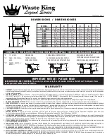
INSTALLATION OF MOUNTING ASSEMBLY

3

Removable 

Splash Guard
Sink Flange

Plumber’s Putty 

(not included)

Sink

Upper Mounting Ring

Mounting Screw

Retainer Ring
Cushion Ring
Lower Mounting Ring

Rubber Gasket

Fiber Gasket

Support Flange

Elbow Flange & Screw Set (2)

Elbow

Spring Clamp Ring

Elbow

Groove

Reset 

Button

OR

TE-45

TE-75S

TE-50

TE-75

TE-125

TE-125BF

NOTE: 

The mounting components are assembled out 

of the box in the same order they will be assembled 

on the sink, so please pay close attention to the 

order of the mounting system components before 

you disassemble them.

The cushion ring and the lower mounting ring 

will remain attached to the disposer during 

installation

. Disassemble the other components 

of the mounting assembly by rotating lower 

mounting ring clockwise until the lower mounting 

ring tabs slide off from the upper mounting ring 

ramp. This will allow you to separate the upper 

assembly from the remaining lower mounting 

assembly.

Unscrew the 3 mounting screws until the upper 

mounting ring can be moved to the top of the 

support flange. Remove the retainer ring with a 

screw driver.

Keep the remaining parts placed together in the 

order they were removed. Before you connect 

the disposer to the mounting assembly under 

the sink, make sure the lower mounting ring is in 

place and the black cushion ring is still engaged 

properly to the top of the disposer opening. (Do 

not remove the cushion ring.)

Be sure the sink is clean. Install a bead of 

plumbers putty to the sink flange (

1

). From top 

of the sink, push the sink flange down against 

the sink opening to make a good seal (

2

). 

Do not 

move or rotate

 the sink flange once it has been 

seated or the seal may be broken.

1

2

Place a heavy object, such as the disposer (use 

a towel to prevent sink scratching) on top of the 

sink flange to hold it down.

Take the remaining portion of the mounting 

assembly, that was put aside. From under the sink 

insert the fibre gasket (

3

), then the support  

flange (

4

), and then the upper mounting ring (

5

).

Hold the three parts in place while attaching the 

retainer ring (

6

) by pulling it apart and sliding it 

onto the sink flange (

7

) until it snaps into the 

groove of the sink flange (

7

).

3
4
5

6

7

8

Tighten the three mounting screws evenly and 

firmly against the supporting flange (

8

). Do not 

over tighten.

Trim off any excess plumber’s putty.

Summary of Contents for TE-125

Page 1: ...Food Waste Disposer User and installation manual EN TE 45 TE 50 TE 75 TE 75S TE 125 TE 125BF IM FRANKE UK 191 ...

Page 2: ... 2 TE 45 TE 50 TE 75 TE 75S TE 125 TE 125BF EN ...

Page 3: ...y information 4 Assembly parts 5 Removal of old unit 6 Plumbing connection 6 Installation of mounting assembly 7 Electrical connection 8 Attaching discharge elbow 10 Air switch operated 10 Operating instructions 11 Continuous feed 11 Batch feed 11 Troubleshooting 12 Cleaning and Maintenance 13 Disposal 13 ...

Page 4: ...ons before using the appliance Z Z To reduce the risk of injury close supervision is necessary when an appliance is used near children Z Z Do not put fingers or hands into a waste disposer Z Z Turn the power switch to the off position before attempting to clear a jam or remove an object from the disposer Z Z When attempting to loosen a jam in a waste disposer use a long wooden object such as a woo...

Page 5: ...on ring and the lower mounting ring will remain attached to the disposer during installation MOUNT TAB DISHWASHER INLET LOWER MOUNTING RING CUSHION RING RETAINER RING MOUNTING SCREWS UPPER MOUNTING RING SUPPORT FLANGE FIBRE GASKET SINK FLANGE REMOVABLE SPLASH GUARD STOPPER ...

Page 6: ...ews push mounting ring up Under it is the snap ring Use screwdriver to pop off ring fig 1D Remove the mounting ring protector ring and gasket from sink flange Some mounts will require the unscrewing of a large ring holding the sink flange in place Pull sink flange up through sink and clean off old putty from sink X X Ensure that sink is clean and thoroughly dry IMPORTANT This is a good time to cle...

Page 7: ... of the support flange Remove the retainer ring with a screw driver Keep the remaining parts placed together in the order they were removed Before you connect the disposer to the mounting assembly under the sink make sure the lower mounting ring is in place and the black cushion ring is still engaged properly to the top of the disposer opening Do not remove the cushion ring Be sure the sink is cle...

Page 8: ... Check with a qualified electrician or serviceman if you are in doubt as to whether the appliance is properly earthed Do not modify the plug provided with the appliance if it will not fit the outlet Have a proper outlet installed by a qualified electrician Earthing instructions FOR WASTE DISPOSERS EQUIPPED WITH AN EARTHED PLUG IN POWER CORD Z Z This appliance must be earthed In the event of a malf...

Page 9: ...erminal that is marked with the letter L 9 9 The blue wire must be attached to the terminal that is marked with the letter N NOTE As your disposer has a molded plug on the lead and the plug is not to be used cut it off and dispose of it wisely A moulded plug with a loose lead with disconnected wires can be hazardous as an electrical shock hazard could occur should such a plug be inserted into a 13...

Page 10: ...A B If not make sure all plumbing connections are tight and in accordance with all plumbing codes and ordinances Run water and check for leaks Air switch operated Disposer Air Switch Assembly The Actuator which consists of 1 Actuator Button 2 Actuator Nut 3 Actuator Outlet Threaded portion THE AIR SWITCH SENSOR ENCLOSURE which is installed into the disposer Only the air tube nozzle is visible from...

Page 11: ...n on a medium flow of cold water X X Scrape in food waste 6A Down the drain go table scraps vegetable peelings cobs rinds pits bones and coffee grounds fig 6A X X Insert stopper to start disposer 6B fig 6B One of the two small slots in stopper base must line up with switch plunger inside the neck of the disposer Push down firmly to turn the disposer on Lift stopper to shut the disposer off X X Run...

Page 12: ...ser Check electrical power switch fuse box or circuit breaker If wiring and electrical components are intact the unit may have internal problems that require service or replacement IF TURNTABLE DOES NOT ROTATE FREELY X X Turn off disposer then check for any foreign object lodged between the turntable and grind ring Dislodge object by rotating table with a wooden broom handle and remove object fig ...

Page 13: ... the competent authority the local refuse disposal service or the vendor of the device Z Z Dispose of the device which is to be discarded via a specialised waste collection point for electronic and electrical devices In accordance with the article of Legislative Decree no 15 dated 25 July Implementation of Directive 2002 96 EC regarding the reduction of the hazardous substances used in in electric...

Page 14: ... 14 TE 45 TE 50 TE 75 TE 75S TE 125 TE 125BF EN TE 75 TE 75S TE 50 TE 125 TE 125BF 345 200 167 70 172 406 200 167 70 172 458 200 220 70 172 371 200 167 70 172 386 158 167 70 140 TE 45 354 132 161 70 137 ...

Page 15: ... 15 TE 45 TE 50 TE 75 TE 75S TE 125 TE 125BF EN ...

Page 16: ... 359 359 Kazakhstan Franke Kazakhstan Ltd 040918 Almaty City Phone 7 727 297 3812 Morocco Franke Kitchen System SARL 21 000 Casablanca Phone 212 522 674 200 Norway Franke Kitchen Systems Norway 8520 Lystrup Denmark Phone 47 35 566 450 Poland Franke Polska Sp z o o 05 090 Raszyn Phone 48 22 711 6700 Portugal Franke Portugal S A 2735 531 Cacém Phone 351 21 426 9670 Romania Franke Romania SRL Panteli...

Reviews: