Power Quality Analyzer
EM-PQ 2300 Operating Manual
FRAKO Kondensatoren- und Anlagenbau www.frako.com
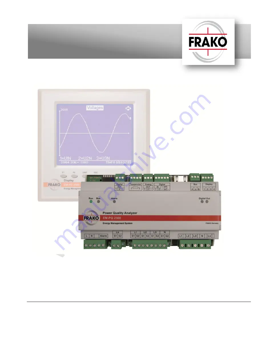
Figure 1: Front view of the EM-PQ 2300 with the optional EM-FD 2500 Display
Page 1: ...Power Quality Analyzer EM PQ 2300 Operating Manual FRAKO Kondensatoren und Anlagenbau www frako com Figure 1 Front view of the EM PQ 2300 with the optional EM FD 2500 Display...
Page 2: ...1 5 1 7 Analog OUT 1 2 21 5 1 8 Digital IN 1 2 Trigger IN tariff switching 21 5 1 9 Temperature IN 22 5 1 10 Alarm 22 6 Commissioning initial start up 23 6 1 Safety precautions before start up 23 6 2...
Page 3: ...ement page 32 8 1 9 Display Energy meter page 32 8 1 10 Display Big display page 32 8 1 11 Display big display page Current page 32 8 1 12 Display big display page Voltage page 32 8 1 13 Display big d...
Page 4: ...Article No 2278555 page 10 Figure 3 Dimensions page 11 Figure 4 Retracting the retaining clips page 12 Figure 5 3 phase connection diagram page 14 Figure 6 Single phase connection diagram page 14 Fig...
Page 5: ...must again be isolated from the power supply Do not expose the instrument to direct sunlight or high temperatures as these could damage it or shorten its service life Do not install the instrument nea...
Page 6: ...ted If the EM PQ 2300 is used in a way not specified in this operating manual the protection supported by the instrument may be adversely affected 1 4 Repair Repairs may not be carried out by the cust...
Page 7: ...easurement range 50 200 C resolution 1 C Earth connection commoned with the digital outputs digital inputs and analogue outputs Active from hardware v1 8 and firmware v1 72 Outputs Digital outputs 2 S...
Page 8: ...mm min 0 14 mm 2 Insulation rating 50 V DC 80 C Digital IN 1 2 Conductor cross section max 1 4 mm min 0 14 mm 2 Insulation rating 50 V DC 80 C Analog OUT 1 2 Conductor cross section max 1 4 mm min 0...
Page 9: ...0 4 6 immunity to conducted disturbances level 10 V RMS 150 kHz 80 MHz EN 61000 4 4 burst immunity 1 kV capacitive coupling 2 kV injection into power supply cable and voltage measurement inputs EN 610...
Page 10: ...EM MC 2200 Maximum Optimizer instruments mounted next to each other on the same DIN rail to be automatically connected to each other It is therefore no longer necessary to wire these connections sepa...
Page 11: ...the Ethernet cable and the type of connector used 4 2 Installing the instrument The EM PQ 2300 is intended for fixed installation in control cabinets or enclosures see Section 4 1 Suitable location pa...
Page 12: ...It is therefore not permitted to connect with other types of DIN rail bus connectors from other manufacturers 5 Installation Prerequisite the instrument has been correctly fitted to the DIN rail as de...
Page 13: ...adequate for the purpose Suitable measures must be taken to prevent cables operating at the power supply voltage being inadvertently pulled out and twisted A disconnecting device such as an isolator o...
Page 14: ...14 Figure 5 3 phase connection diagram Figure 6 Single phase connection diagram...
Page 15: ...ency 45 65 Hz or 100 360 V DC absolute limits It is connected to terminals L and N as shown in the diagrams Figure 5 or Figure 6 page 14 CAUTION The cables leading to the instrument must be permanentl...
Page 16: ...y advisable when the phases are symmetrically loaded since as a rule the phase neutral voltages here are near to each other in value NOTE The voltage measurement inputs not in use must be commoned wit...
Page 17: ...screws on the sides of the connectors for the current transformer circuits must always be tightened before the instrument is put into service Tightening these retaining screws prevents the connectors...
Page 18: ...n between a PC and the EM PQ 2300 using either an EMIS 1500 Central Unit data collector and bus coupler or an EMG 1500 PN Gateway Ethernet bus coupler This is a practical solution if the FRAKO Starkst...
Page 19: ...nded cable types Surge impedance 100 120 0 5 mm shielded twisted pairs Types IBM Twinax EIB bus cable Lapp Unitronic J 2Y ST Y Siemens YCYM 4 2 0 8 or PYCYM 4 2 0 8 NOTE A mixing of different cable ty...
Page 20: ...p lines and star topologies are not permitted The total length of the bus must not exceed 40 m See Section 5 1 5 2 Cable types below for the cable types to be used and their limitations At the beginni...
Page 21: ...pulses as per DIN 43864 which can be used to transmit status codes The assignment of status codes to the digital outputs is carried out using the FRAKO configuration software Device Manager For techni...
Page 22: ...nfiguration being possible If a 2 wire configuration is used each outer connection must be commoned with the inner connection next to it For technical data see Section 2 Technical data page 7 for conf...
Page 23: ...tarts flashing at 1 second intervals If an EM FD 2500 Display instrument is connected a red LED located on the base near the Display connector serves as an overcurrent annunciator If it lights up or f...
Page 24: ...e an IP address Even if a network cable is connected later depending on the firmware version there is no automatic IP address assignment Only after switching the EM PQ 2300 off and on with the network...
Page 25: ...r incorporated in the EM FD 2500 is activated and deactivated using that instrument s keys Please refer to the EM FD 2500 operating manual for the procedure NOTE In the EM FD 2500 Display as delivered...
Page 26: ...eds a unique IP address The simplest way to set this is via the optional EM FD 2500 Display If this instrument is not installed the IP address can be assigned by DHCP or by using the Device Manage sof...
Page 27: ...th a crossover cable If not yet done install FRAKO Device Manager on the PC Move DIP switch 3 on the EM PQ 2300 to ON The instrument now has the IP address 192 168 0 57 Note the IP settings of the PC...
Page 28: ...play bus It is possible to interrogate for the assigned address at the EM FD 2500 Display The procedure is described in the EM FD 2500 operating manual 7 1 3 1 Terminating resistors on the Display bus...
Page 29: ...ice name so that it can be identified uniquely just by its first 16 characters After the device has been selected the keys have the following functions Taste Function F1 SET UP Opens the Display Set u...
Page 30: ...ils it sends can be switched between German and English Please note that after the language has been changed at the Display or via EMPQ SW the Display language does not change until the Unit key is pr...
Page 31: ...f current harmonics in the neutral conductor N 8 1 6 Display Harmonics page Selecting the menu item Harmonics in Display opens this page Pressing the ESC key will close the page and return the user to...
Page 32: ...supply Q ind Inductive reactive energy in kvarh Q cap Capacitive reactive energy in kvarh Q eff RMS reactive energy in kvarh S Apparent energy in kVAh 8 1 10 Display Big display page Selecting the me...
Page 33: ...e Selecting the menu item Active alarms in Display opens this page Pressing the ESC key will close the page and return the user to the next higher menu level The alarms currently present are displayed...
Page 34: ...ings Events Recorded events System log System messages Configuration Download SNMP MIB Operating manual Modbus address table Firmware Firmware update 8 2 2 Operation The measurement readings are prese...
Page 35: ...life threatening If the above instructions are followed the risk of endangering life and limb can be significantly reduced The instrument may only be cleaned with a dry cloth When this is done the ab...
Page 36: ...threatening Observing the above safety precautions can significantly reduce the risk to life and limb An internal fuse is fitted in the EM PQ 2300 It is mounted in a fuseholder underneath the hinged c...
Page 37: ...disconnected from the instrument All disconnected cables must be individually isolated and insulated and measures must be taken to prevent their inadvertent contact with live components or electricall...
Page 38: ...11 General operating notes The following points must be observed when operating the instrument The instrument must always be operated in a closed control cabinet as described in Section 4 Mounting th...
Page 39: ...ess already assigned to another device Disconnect the EM PQ 2300 from the bus and check the bus addresses with Device Manager Is the address assigned to the EM PQ 2300 still displayed If yes assign a...
Page 40: ...omponents Measuring Instruments and Power Quality Analysers Power Quality EMS ISO 50001 FRAKO 55 02675 08 18 9893 Technische nderungen vorbehalten FRAKO Kondensatoren und Anlagenbau GmbH Tscheulinstra...