background image

Deutsch

29

4. INSTALLATION DES PRODUKTS

4.1 In der Verpackung sind die folgenden Produkte enthalten: 

•  Modul 3DG-PS-BU

•  Stromkabel

•  Hinweise zur Sicherheit und Installation des Produkts

4.2 Montage des Moduls

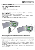
ES WIRD DARAN ERINNERT, DASS DAS MODUL 3DG-PS-BU IN DEN LETZTEN SLOT DER KOPFSTELLE 

EINGESETZT WERDEN MUSS.

1-Die Stromversorgung der Kopfstelle abtrennen (wenn angeschlossen).

2-Das Modul auf dem letzten Slot der Kopfstelle montieren und mit den im Lieferumfang enthaltenen 

Schrauben befestigen.

3-Der Kopfstelle und dem Modul mit den entsprechenden Stromkabeln Strom zuführen. 

5. GEBRAUCHSANLEITUNGEN

Den Strom an der Kopfstelle und dem Modul einschalten und abwarten, bis beide hochgefahren sind (auf 

dem Display des Steuergeräts wird das Logo von Fracarro angezeigt), dann kann auf das Menü der Kopfstelle 

zugegriffen werden: 

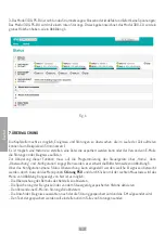
 Auf das Menü zugreifen, die Taste “√ ” drücken, den Nutzercode eingeben (Default 1234) und mit “√” bestätigen.

  Die Kopfstelle nimmt einen Scan vor, um die vorhandenen Module zu finden, das Modul 3DG-PS-BU wird in die 

Position 6 gebracht.

 en Status des Moduls nach der Farbe der LED, die auf dem Frontelement desselben Moduls vorhanden ist, 

kontrollieren, wie in Tabelle 1. 


Summary of Contents for 3DG-PS-BU

Page 1: ...ISTRUZIONI PER L USO OPERATING INSTRUCTIONS INSTRUCTIONS D EMPLOI BEDIENUNGSANLEITUNG 3DG PS BU ...

Page 2: ...Descrizione scheda 4 3 2 Descrizione LED 4 INSTALLAZIONE DEL PRODOTTO 5 4 1 Contenuto della confezione 5 4 2 Montaggio modulo 5 ISTRUZIONI PER L UTILIZZO 5 INTERFACCIA WEB 6 6 1 Connessione WEB INTERFACE 6 6 2 Menu HOME 6 MONITORAGGIO 8 SPECIFICHE TECNICHE 9 CONFORMITA ALLE NORMATIVE EUROPEE 36 ...

Page 3: ... istruzioni di montaggio riportate nel Capitolo 3 Per APPARECCHIATURE INSTALLATE PERMANENTEMENTE un dispositivo di sezionamento facilmente accessibile deve essere incorporato all sterno dell apparecchiatura per APPARECCHIATURE CON SPINA DI CORRENTE la presa deve essere installata vicino all apparecchiatura ed essere facilmente accessibile ll cestello sul quale sarà installato il prodotto deve esse...

Page 4: ...ingresso di rete elettrica indipendente da quello della Control Unit e di un led multifunzione che ne indica lo stato di funzionamento Il modulo è compatibile solo con le centrali 3DG FLEX che montano la Control Unit EVO la sua installazione in centrali con Control Unit antecedenti potrebbe comprometterne il funzionamento 3 1 Descrizione Scheda 3 2 Descrizione Led LED STATO INGRESSI Led INDICAZION...

Page 5: ...to funzionamento dei moduli e per garantire un adeguata schermatura contro le interferenze radio è necessario fissare il modulo con le viti fornite Vite Inferiore Vite superiore Inserire con attenzione nella guida dell alloggiamento 5 ISTRUZIONI PER L UTILIZZO Una volta alimentata la centrale ed il modulo si deve attendere l inizializzazione di entrambe compare il logo Fracarro sul display della Co...

Page 6: ...centrale per renderli compatibili nella stessa sottorete così che possano comunicare Ad esempio a Parametri impostati nelle proprietà della scheda di rete del PC IP 192 168 0 3 SUBNET MASK 255 255 255 0 GATEWAY 192 168 0 1 b Parametri da impostare nella control unit IP 192 168 0 2 SUBNET MASK 255 255 255 0 GATEWAY 192 168 0 1 3 Avviare il browser internet browser consigliati Google Chrome Mozilla ...

Page 7: ...e elettrica e funzionanti la visualizzazione nella schermata HOME sarà quella riportata in figura 2 Fig 2 2 L alimentatore della Control Unit non è collegato alla rete elettrica od è difettoso e non eroga tensioni Il modulo 3DG CU verrà evidenziato con un triangolo rosso di anomalia il modulo 3DG PS BU avrà il segno di spunta verde come in Figura 3 Fig 3 ...

Page 8: ...ione è necessario entrare nella programmazione della control unit da Home poi Monitoraggio e Configurazione apparirà la schermata di figura 5 Dal menu di configurazione Stato monitoraggio è possibile impostare quali eventi monitorare selezionando la voce malfunzionamento PSU e cliccandoci sopra con il tasto destro del mouse comparirà il menu di figura 6 in cui è possibile Abilitare il monitoraggio...

Page 9: ...liano 7 SPECIFICHE TECNICHE Temperatura operativa C 5 45 Tensione di alimentazione V 230 Frequenza di alimentazione Hz 50 60 Classe di isolamento Classe II Massimo consumo W 135 Dimensioni mm 246 x 52 x 209 ...

Page 10: ...description 12 3 2 LED description 12 INSTALLING THE PRODUCT 13 4 1 Contents of the packaging 13 4 2 Module mounting 13 OPERATING INSTRUCTIONS 13 WEB INTERFACE 14 6 1 WEB INTERFACE CONNECTION 14 6 2 HOME Menu 14 MONITORING 16 TECHNICAL SPECIFICATIONS 17 COMPLIANCE TO EUROPEAN DIRECTIVES 36 ...

Page 11: ...essible power disconnecting switch easy to reach UNITS WITH A POWER PLUG the outlet must be installed near the unit and easy to reach The cabinet where the product is installed must be connected either directly or by means of the rack to the earth electrode of the antenna installation according to the EN 60728 11 regulation The earth screw is indicated with the symbol It is important to observe th...

Page 12: ... equipped with an electrical input independent of the Control Unit and with a multifunctional LED that shows its operating status The module is only compatible with the 3DG FLEX control units that mount the Control Unit EVO its installation in units with previous Control Units could compromise its operation 3 1 Chart description 3 2 LED description INPUT LED STATUS Led INDICATION Off No power on b...

Page 13: ...y using the supplied screws 3 Charge the control unit and the module by using the proper power cables 5 OPERATING INSTRUCTIONS After the control unit and the module are powered wait for the initialization of both of them the logo Fracarro appears on the display of the Control Unit now you can enter the control unit menu access the menu press the button enter your user code default code1234 and the...

Page 14: ... compatible in the same subnetwork so that they can communicate For example a The parameters set in the network card of the PC IP 192 168 0 3 SUBNET MASK 255 255 255 0 GATEWAY 192 168 0 1 b Parameters to set in the control unit IP 192 168 0 2 SUBNET MASK 255 255 255 0 GATEWAY 192 168 0 1 3 Start the Internet browser recommended browsers Google Chrome Mozilla 4 Enter the IP address associated to th...

Page 15: ...display in the HOME window will be as given in figure 2 Fig 2 2 The control Unit s feeder is not connected to the electrical network or is not working properly and does not supply power The 3DG CU module will be shown with a red triangle which means an anomaly is occurring the 3DG PS BU module will have a green tick as given in Figure 3 Fig 3 ...

Page 16: ... failures or events To enable this function enter programming of the control unit from Home then Monitoring and Configuration the window given in figure 5 will appear From the configuration menu and Monitoring Status you can set which events should be monitored Select the PSU malfunctioning and right click it with the mouse the menu given in Figure 6 will appear From this menu you can do the follo...

Page 17: ...English 17 7 TECHNICAL SPECIFICATIONS Operating temperatures C 5 45 Voltage V 230 Power supply frequency Hz 50 60 Insulation class Class II Maximum consumption W 135 Dimensions mm 246x52x209 ...

Page 18: ...ption de la fiche 20 3 2 Description LED 20 INSTALLATION DU PRODUIT 21 4 1 description du module 21 4 2 Montage du module 21 INSTRUCTIONS D UTILISATION 21 INTERFACE WEB 22 6 1 Connexion à l INTERFACE WEB 22 6 2 Menu ACCUEIL 22 MONITORAGE 24 SPÉCIFICATION TECHNIQUES 25 CONFORMITÉ AUX DIRECTIVES EUROPÉENNES 36 ...

Page 19: ...rites au Chapitre 3 Pour des APPAREILS INSTALLÉS DE FAÇON PERMANENTE un dispositif de sectionnement facilement ac cessible doit être incorporé à l extérieur de l appareil pour des APPAREILS AVEC UNE PRISE DE COURANT la prise doit être installée à proximité de l appareil et être facilement accessible L armoire dans laquelle le produit est installé doit être raccordée directement ou à travers le rac...

Page 20: ... d une entrée secteur indépendante de celle de l Unité de Contrôle et d une led multifonctions qui indique l état de fonctionnement Le module n est compatible qu avec les stations 3DG FLEX dotées de l Unité de Contrôle EVO S il est installé dans des stations avec des Unités de Contrôle précédentes son fonctionnement pourrait être compromis 3 1 Description de la fiche 3 2 Description LED LED STATO ...

Page 21: ...enter la station et le module au moyen des câbles d alimentation spécifiques 5 INSTRUCTIONS D UTILISATION Après avoir alimenté la station et le module attendre leur initialisation le logo Fracarro est affiché sur l écran de l Unité de Contrôle À ce stade il est possible d accéder au menu de la station accéder au menu appuyer sur la touche et taper le code utilisateur par défaut 1234 puis confirmer...

Page 22: ...les rendre compatibles dans le même sous réseau et pouvoir communiquer Par exemple a Paramètres réglés dans les propriétés de la carte réseau du PC IP 192 168 0 3 SUBNET MASK 255 255 255 0 GATEWAY 192 168 0 1 b Paramètres à programmer dans l unité de contrôle IP 192 168 0 2 SUBNET MASK 255 255 255 0 GATEWAY 192 168 0 1 3 Lancer le navigateur Internet navigateurs conseillés Google Chrome Mozilla 4 ...

Page 23: ...nction la page écran ACCUEIL sera affichée comme montré sur la figure 2 Fig 2 2 L alimentation de l Unité de Contrôle n est pas branchée au secteur ou elle est défectueuse et elle ne fournit pas de tension Le module 3DG CU sera mis en évidence avec un triangle rouge d anomalie le module 3DG PS BU aura une marque de contrôle verte comme sur la figure 3 Fig 3 ...

Page 24: ...ation de l Unité de Contrôle depuis l Accueil puis accéder aux pages Suivi et Configuration enfin la page écran de la figure 5 apparaît Depuis le menu de configuration État du Monitorage il est possible de programmer les événements à suivre en sélectionnant la rubrique mauvais fonctionnement PSU et en cliquant sur cette rubrique avec la touche droite de la souris le menu de la figure 6 apparaît De...

Page 25: ...5 7 SPÉCIFICATIONS TECHNIQUES Température opérationnelle C 5 45 Tension d alimentation V 230 Fréquence d alimentation Hz 50 60 Classe d isolation Classe II Consommation maximale W 135 Dimensions mm 246 x 52 x 209 ...

Page 26: ...eibung der Karte 28 3 2 Beschreibung der LEDs 28 INSTALLATION DES PRODUKTS 29 4 1 Packungsinhalt 29 4 2 Montage des Moduls 29 GEBRAUCHSANLEITUNGEN 29 WEB INTERFACE 30 6 1 Verbindung zum WEB INTERFACE 30 6 2 Menü HOME 30 ÜBERWACHUNG 32 TECHNISCHE DATEN 33 KONFORMITÄT MIT DEN EUROPÄISCHEN RICHTLINIEN 36 ...

Page 27: ...en installiert werden Für PERMANENT INSTALLIERTE GERÄTE muss eine leicht zugängliche Trennungsvorrichtung außen in das Gerät eingebaut werden für GERÄTE MIT STROMSTECKER muss die Steckdose neben dem Gerät und leicht zugänglich installiert werden Das Gestell auf dem das Produkt installiert wird muss direkt oder durch den Rack an der Erdungselektrode der Antennenanlage in Konformität mit der Richtli...

Page 28: ...ingang der unabhängig von dem des Steuergeräts ist und mit einer Multifunktions LED ausgestattet die den Betriebsstatus anzeigt Das Modul ist ausschließlich mit den Kopfstellen 3DG FLEX kompatibel die das EVO Steuergerät montieren die Installation in Kopfstellen mit vorherigen Steuergeräten kann die Funktionstüchtigkeit beeinträchtigen 3 1 Beschreibung der Karte 3 2 Beschreibung der LEDs LED STATO...

Page 29: ...festigen 3 Der Kopfstelle und dem Modul mit den entsprechenden Stromkabeln Strom zuführen 5 GEBRAUCHSANLEITUNGEN Den Strom an der Kopfstelle und dem Modul einschalten und abwarten bis beide hochgefahren sind auf dem Display des Steuergeräts wird das Logo von Fracarro angezeigt dann kann auf das Menü der Kopfstelle zugegriffen werden Auf das Menü zugreifen die Taste drücken den Nutzercode eingeben ...

Page 30: ... 5E oder über einen Netzwerkswitch an das Steuergerät anschließen 2 Die IP Adresse des PCs oder des Steuergeräts ändern damit sie mit dem gleichen Subnet kompatibel sind und miteinander kommunizieren können Zum Beispiel a Eingestellte Parameter in den Eigenschaften der Netzkarte vom PC IP 192 168 0 3 SUBNET MASK 255 255 255 0 GATEWAY 192 168 0 1 b Parameter die am Steuergerät eingestellt werden mü...

Page 31: ...prechenden Anzeigen auftreten 1 Sowohl das Modul 3DG PS BU als auch das Netzteil des Steuergeräts sind an das Stromnetz angeschlossen und funktionieren die Anzeige auf der Bildschirmseite HOME wird derjenigen in Abbildung 2 entsprechen Fig 2 2 Das Netzteil des Steuergeräts ist nicht an das Stromnetz angeschlossen oder ist defekt und liefert keine Spannungen Das Modul 3DG CU wird mit einem roten St...

Page 32: ...auf die Programmierung des Steuergeräts über Home dann Überwachung und Konfiguration zugegriffen werden es erscheint die Bildschirmseite von Abbildung 5 Über das Konfigurationsmenü Status Überwachung kann eingestellt werden welche Ereignisse überwacht werden durch Auswahl des Menüpunkts Störung PSU und durch Klicken mit der rechten Maustaste wird das Menü von Abbildung 6 angezeigt von hier ist es ...

Page 33: ...Deutsch 33 7 Technische Daten Betriebstemperatur C 5 45 Speisespannung V 230 Stromfrequenz Hz 50 60 Isolationsklasse Klasse II Max Stromverbrauch W 135 Abmessungen mm 246 x 52 x 209 ...

Page 34: ...34 ...

Page 35: ...35 ...

Page 36: ...ura INFORMATION FOR THE USERS According to the Art 26 of the Law Decree 14th March 2014 Application of the 2012 19 EU directive relevant to disposal of old electrical and electronic equipment RAEE This symbol on the product or on its packaging indicates that this product shall not be treated as household waste Instead it shall be handed over to the applicable collection point or to the shop when a...

Reviews: