background image


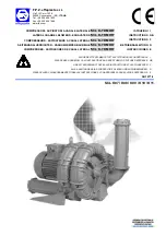
COMPRESSORI - ASPIRATORI A CANALE LATERALE 

‘SCL K-TD MOR’

ISTRUZIONI  I 

LATERAL CHANNEL BLOWERS - EXHAUSTERS 

‘SCL K-TD MOR’

INSTRUCTIONS  GB

COMPRESSEURS - ASPIRATEURS A CANAL LATERAL 

‘SCL K-TD MOR’

INSTRUCTIONS  F 

SEITENKANALVERDICHTER - VAKUUMPUMPEN BAUREIHE 

‘SCL K-TD MOR’

BETRIEBSANLEITUNG  D 

COMPRESORES - ASPIRADORES DE CANAL LATERAL 

‘SCL K-TD MOR’

INSTRUCCIONES  E 


LEGGERE ATTENTAMENTE TUTTE LE ISTRUZIONI E CONSERVARLE I 

PLEASE READ CAREFULLY ALL INSTRUCTIONS AND KEEP THEM FOR FUTURE REFERENCE GB 

LIRE ATTENTIVEMENT TOUTES LES INSTRUCTIONS ET LES CONSERVER F 

ALLE ANLEITUNGEN SIND SORGFÄLTIG ZU LESEN UND AUFZUBEWAHREN! D 

SIRVASE LEER CUIDADOSAMENTE TODAS LAS INSTRUCCIONES Y CONSERVARLAS PARA FUTURA REFERENCIA E 

SN 1977-0 


®


F.P.Z. effepizeta s.r.l. 

Via F.lli Cervi 16/18 
20049 Concorezzo - (MI) - 

ITALIA


Tel. +39 039 604 1820 
Fax +39 039 604 1296 
www.fpz.com


SCL K07 / K08 / K09 / K10 / K11

Summary of Contents for SCL K-TD MOR Series

Page 1: ...MOR INSTRUCCIONES E LEGGERE ATTENTAMENTE TUTTE LE ISTRUZIONI E CONSERVARLE I PLEASE READ CAREFULLY ALL INSTRUCTIONS AND KEEP THEM FOR FUTURE REFERENCE GB LIRE ATTENTIVEMENT TOUTES LES INSTRUCTIONS ET...

Page 2: ...servizio prima che la macchina in cui sar incorporata sia dichiarata conforme con le citate Direttive 2 Sottoposta a collaudo funzionale risultata conforme alle caratteristiche richieste 1 The unit c...

Page 3: ...390 390 78 7 80 7 0 28 2 8 105 0 11 0 12 7 550 475 490 79 5 81 5 0 28 2 8 105 5 SCL K08 TD 15 0 17 4 650 650 80 3 82 3 0 28 2 8 110 5 9 2 10 6 300 300 240 240 80 4 82 4 0 28 2 8 115 5 11 0 12 7 390 39...

Page 4: ...5 75 80 1 78 1 82 7 199 50 10 10 7 0 110 8 1 110 80 4 78 4 82 7 210 50 SCL K08 TD 15 15 12 5 185 13 6 185 81 5 79 5 82 7 232 60 15 15 7 7 125 9 2 125 82 7 80 7 82 7 255 70 20 20 11 7 180 13 2 180 83...

Page 5: ...IONE 8 2 1 COMPRESSORE 8 2 2 COMPRESSORE IN PARALLELO 8 2 3 ASPIRATORE 8 2 4 ASPIRATORE IN PARALLELO 8 2 5 LEGENDA ACCESSORI 8 3 ISTRUZIONI PER LA MESSA IN FUNZIONE 9 3 1 MESSA IN FUNZIONE CON COLLETT...

Page 6: ...atteristiche sono soggette a variazione in funzione dei seguenti fattori variazione della pressione assoluta di aspirazione o di scarico rispetto alla condizione di riferimento 1013 mbar funzionamento...

Page 7: ...ondizioni nominali scostamenti dalle suddette condizioni possono comportare variazioni fino al 10 Si possono riscontrare piccole differenze tra i valori di misura delle fasi tollerabili fino a differe...

Page 8: ...LO 2 5 LEGENDA ACCESSORI 2 3 ASPIRATORE 2 4 ASPIRATORE IN PARALLELO I 8 49 Item Denominazione Item Denominazione 1 Filtro Filtro in linea 5 Valvola di sicurezza 2 Silenziatore 6 Valvola di ritegno 3 M...

Page 9: ...azione della soffiante 3 Individuare la disposizione che interessa fig 1 fig 2 fig 3 4 Porre il collettore 706 con il fusto silenziatore d aspirazione 700 sulla guarnizione 424 e bloccare il tutto ser...

Page 10: ...estrattore e la linguetta 940 6 Rimuovere le viti 902 poste sul coperchio intermedio 104 7 Rimuovere i componenti 103 e 104 e tenerli uniti facendo leva nelle 2 apposite cavit presenti tra coperchio i...

Page 11: ...onenti 103 e 104 e tenerli uniti facendo leva nelle 2 apposite cavit presenti tra coperchio intermedio 104 e corpo 161 9 In caso si renda necessario rimuovere i piedi 183 rimuovere le viti 920 con i d...

Page 12: ...Asportare i silenziatori dall unit facendo attenzione di non perdere le guarnizioni 424 4 Estrarre i panni 720 dai fusti silenziatori 5 Recuperare i retini di sostegno 710 6 Sostituire e riassemblare...

Page 13: ...tura dell aria di mandata elevata L unit sta operando ad una pressione depressione superiore al valore ammesso Il filtro d aspirazione intasato I unit ha accumulato depositi interni Tubazioni di aspir...

Page 14: ...TION SKETCHES 17 2 1 PRESSURE SERVICE 17 2 2 PARALLEL PRESSURE SERVICE 17 2 3 VACUUM SERVICE 17 2 4 PARALLEL VACUUM SERVICE 17 2 5 LIST ACCESSORIES 17 3 SET UP INSTRUCTIONS 18 3 1 START UP WITH 90 MAN...

Page 15: ...lve The performance characteristics are liable to variations due to the following factors Differences of the suction or discharge pressures from the reference conditions 1013 mbar Operation in a syste...

Page 16: ...rs to normal operating conditions Departures from the nominal operating conditions can result in variations of 10 There can be small differences in the measured value of each phase These are tolerable...

Page 17: ...SSURE SERVICE 2 5 LIST ACCESSORIES 2 3 VACUUM SERVICE 2 4 PARALLEL VACUUM SERVICE GB 17 49 Item Denomination Item Denomination 1 Filter Inline filter 5 Safety valve 2 Silencer 6 Non return valve 3 Fle...

Page 18: ...3 Select the desired orientation see Fig 1 Fig 2 Fig 3 4 Place the 706 manifold with the 700 silencer housing on 424 gasket and seal all the way around with 426 screws using the key ch13 as provided 3...

Page 19: ...ing a puller and 940 key 6 Remove the 902 screws placed on 104 intermediate cover 7 Remove the 103 and 104 and place them together by using the two holes between 104 intermediate cover and 161 housing...

Page 20: ...the 103 and 104 and place them together by using the two holes between 104 intermediate cover and 161 housing 9 If needed remove the 183 mounting feet by removing 920 screws and 921 nuts 10 Remove the...

Page 21: ...encers from the unit being careful not to lose the 424 gaskets 4 Extract the 720 panels from the silencer housings 5 Clean up the 710 retaining screen 6 Replace and reassemble proceeding in reverse or...

Page 22: ...Delivery air temperature high The unit is operating at a pressure vacuum that exceeds that allowed Intake filter clogged Deposits have built up inside the unit Intake and or delivery piping clogged Ai...

Page 23: ...LATION 26 2 1 SOUFFLANTE 26 2 2 SOUFFLANTE EN PARALL LE 26 2 3 POMPE VIDE 26 2 4 POMPE VIDE EN PARALL LE 26 2 5 LISTE DES ACCESSOIRES 26 3 INSTRUCTIONS POUR LA MISE EN MARCHE 27 3 1 MISE EN MARCHE AVE...

Page 24: ...sont sujettes variations en fonction des facteurs suivants Variations de la pression absolue d aspiration ou de d charge par rapport la condition de r f rence 1013 mbar Fonctionnement par syst me mixt...

Page 25: ...s indiqu es ci dessus sont acceptables si les variations ne d passent pas 10 Les valeurs mesur es des phases peuvent supporter de petits carts jusqu 9 se reporter IEC 34 1 1 4 MISE EN SERVICE Lors de...

Page 26: ...5 LISTE DES ACCESSOIRES 2 3 POMPE VIDE 2 4 POMPE VIDE EN PARALL LE Item Denomination Item Denomination 1 Filtre Filtre ad air 5 Soupape de s curit 2 Silencieux suppl mentaire 6 Clapet anti retour 3 M...

Page 27: ...424 sur la bouche d aspiration de la soufflante 3 Rep rer la disposition recherch e fig 1 Fig 2 Fig 3 4 Mettre l adaptateur 706 avec le corps silencieux 700 sur joint 424 et la bloquer en serrant ave...

Page 28: ...teur et la languette 940 6 Oter les vis 902 de la flasque interm diaire 104 7 Retirer les composants 103 et 104 et les laisser ensemble en faisant levier dans les 2 gorges situ es entre le couvercle i...

Page 29: ...ensemble en faisant levier dans les 2 gorges situ es entre le couvercle interm diaire 104 et le corps 161 9 En cas de n cessit enlever les pieds 183 ter les vis 920 et crous 921 10 Enlever la pi ce d...

Page 30: ...eux de l unit en faisant attention de ne pas perdre les joints 424 4 Extraire les mousses 720 des corps de silencieux 5 R cup rer les grillages 710 6 Remplacer et remonter en proc dant dans l ordre in...

Page 31: ...v e L unit travaille avec une pression et ou d pression sup rieure la valeur admise Le filtre d aspiration est bouch Des d p ts se sont accumul s l int rieur de l unit Les tuyaux d aspiration et ou de...

Page 32: ...L ARBEITENDER VERDICHTER 35 2 3 SERIELL ARBEITENDER VERDICHTER 35 2 4 VAKUUMPUMPE 35 2 5 PARALLEL ARBEITENDE VAKUUMPUMPE 35 2 6 ZUBEH RLISTE 35 3 ANLEITUNGEN F R INBETRIEBNAHME 36 3 1 INBETRIEBNAHME M...

Page 33: ...EN BESONDERS BEI MASCHINEN F R HOHE DR CKE IST UNBEDINGT ZU VERMEIDEN Es sind geeignete Sicherheitsventile vorzusehen Die Gebl seleistung h ngt von folgenden Faktoren ab Abweichen der absoluten Saug o...

Page 34: ...LENDEM MOTORSCHUTZ VERF LLT DIE GESAMTE GARANTIE 1 3 2 1 STROMMESSUNG Die Stromaufnahme gilt f r den Betrieb unter Nennbedingungen Sie kann sich bei Abweichung um bis zu 10 ndern Unterschiede zwischen...

Page 35: ...2 5 ZUBEH RLISTE 2 3 VAKUUMPUMPE 2 4 PARALLEL ARBEITENDE VAKUUMPUMPE D 35 49 Item Kennzeichnung Item Kennzeichnung 1 Filter In line Filter 5 Sicherheitsventil 2 Schalld mpfer 6 R ckschlagklappe 3 Elas...

Page 36: ...nschte Position ausw hlen siehe Bild 1 Bild 2 und Bild 3 4 Die Baugruppe Anschlu bogen Pos 706 und Schalld mpfergeh use Pos 700 auf die Dichtung Pos 424 aufsetzen und unter Verwendung des mitgeliefert...

Page 37: ...fernen Sie die Komponenten Pos 103 und Pos 104 gemeinsam indem Sie Hebel in den Beiden gegen berliegenden Aussparungen zwischen dem Zwischengeh usedeckel Pos 104 und Geh use Pos 161 8 Falls notwendig...

Page 38: ...n dem Zwischengeh usedeckel Pos 104 und Geh use Pos 161 9 Falls notwendig entfernen Sie die Befestigungskonsolen Pos 183 Dazu m ssen die Schrauben Pos 920 mit den Muttern Pos 921 gel st und entfernt w...

Page 39: ...meins tze Pos 720 aus den Schalld mpfergeh usen Pos 700 5 Entnehmen Sie die St tzgitter Pos 710 aus den Schalld mmeins tzen 6 Ersetzen Sie die Schalld mmeins tze und montieren Sie die Schalld mpfergeh...

Page 40: ...gat arbeitet bei einem Druck bzw Unterdruck der h her ist als der zugelassene Wert Der Absaugfilter ist verstopft im Aggregat haben sich Ablagerungen angesammelt Absaug oder Zufuhrleitungen verstopft...

Page 41: ...4 2 1 COMPRESOR 44 2 2 COMPRESOR EN PARALELO 44 2 3 ASPIRADOR 44 2 4 ASPIRADOR EN PARALELO 44 2 5 TABLA ACCESORIOS 44 3 INSTRUCCIONES PARA LA PUESTA EN SERVICIO 45 3 1 PUESTA EN SERVICIO CON COLECTOR...

Page 42: ...aracter sticas de actuaci n est n sujetas a variaciones debido a los factores Diferencias de las presiones de aspiraci n o descarga de las condiciones de referencia 1013 mbar Funcionamiento a sistema...

Page 43: ...refiere a condiciones de funcionamiento normales Las salidas de las condiciones de funcionamiento nominal pueden resultar en variaciones del 10 Pueden existir peque as diferencias en el valor medio d...

Page 44: ...ELO 2 5 TABLA ACCESORIOS 2 3 ASPIRADOR 2 4 ASPIRADOR EN PARALELO Item Denominaci n Item Denominaci n 1 Filtro Filtro en l nea 5 V lvula de seguridad 2 Silenciador 6 V lvula de retenci n 3 Manguito fle...

Page 45: ...24 sobre la boca de aspiraci n del soplador 3 Individuar la disposici n che le interesa fig 2 fig 3 fig 4 4 Colocar el conjunto colector silenciador sobre la junta de estanqueidad 424 y bloquear cerra...

Page 46: ...g eta 940 6 Quitar los pernos 902 situados en la tapa intermedia 104 7 Quitar los componentes 103 y 104 manteni ndolos juntos y haciendo palanca en las dos ranuras entre la tapa intermedia 104 y la ca...

Page 47: ...ndo palanca en las dos ranuras entre la tapa intermedia 104 y la caja 161 9 Si se hace necesario quitar los pies 183 quitar los pernos 920 y las tuercas 921 10 Quitar el distancial 934 11 Quitar las a...

Page 48: ...nta de estanqueidad 424 del aparato 4 Extraer el material 720 del cuerpo silenciador 5 Retener la red de sujeci n 710 6 Cambiar el material y montar nuevamente las piezas siguiendo las instrucciones a...

Page 49: ...mpulsi n elevada La unidad est trabajando con una presi n y o depresi n superior al valor admitido El filtro de aspiraci n est obstruido En la unidad se han acumulado dep sitos internos Tubos de aspir...

Reviews: