background image

67

Model LR16 [Recorder functions / Project management]

[MENU] dial

numeric keys

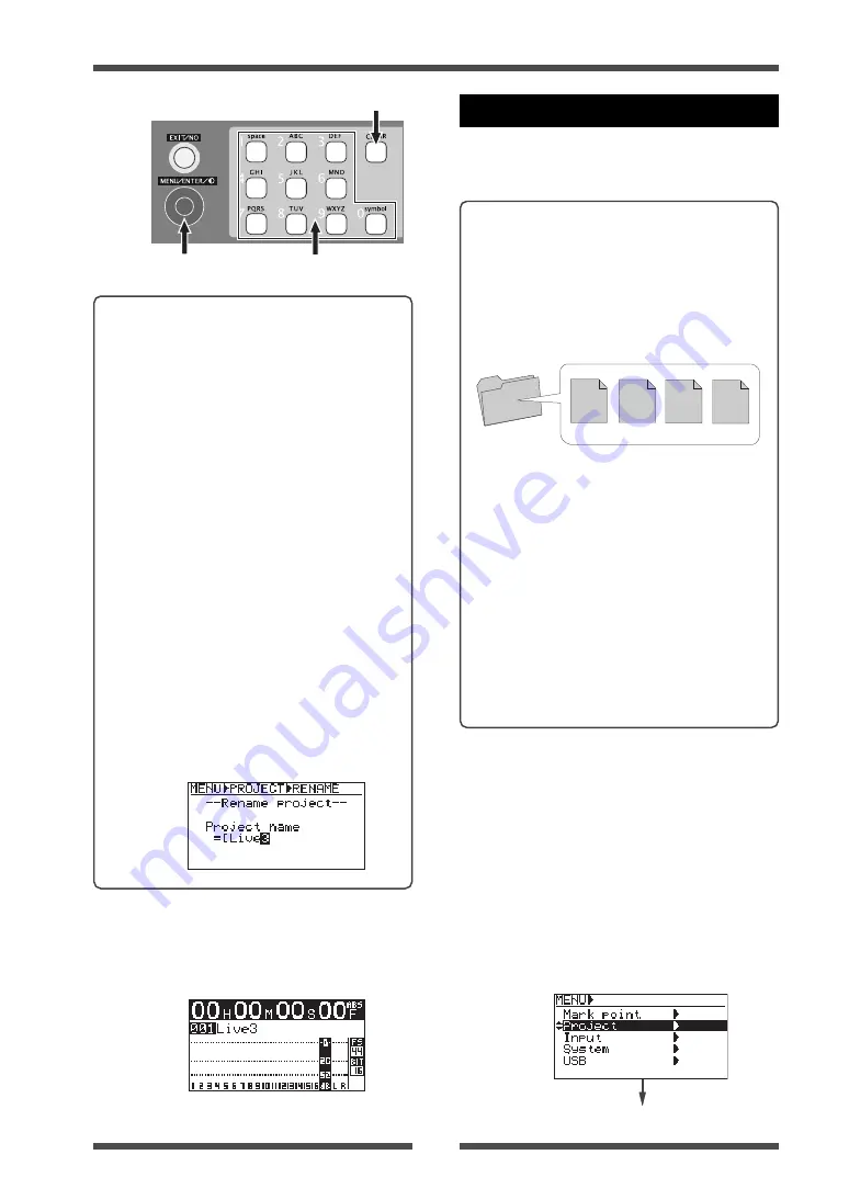
(5)

After editing the name, press the [ENTER]
key.

The display now shows the Home screen of
the renamed project.

[CLEAR] key

<Name editing example>

The following shows the procedure of com-
pletely deleting "PROJ001", the current
project name, and entering "Live3" as the
new name.

(1) Rotate the [MENU] dial counterclockwise

to move the cursor to the leftmost position.

(2) Press the [CLEAR] key repeatedly until all

characters of the current name are deleted.

(3) Use the "5" key to enter an uppercase "L".

(4) Use the "4" key to enter a lowercase "i".

(5) Use the "8" key to enter a lowercase "v".

(6) Use the "3" key to enter a lowercase "e".

(7) Use the [MENU] dial to move the cursor to

the right.

(8) Use the "3" key to enter a "3".

Rolling back a project

Instead of the undo/redo function, you can
retrieve the pre-edited condition of an edited
project.

<Memo>: 

Each time you perform recording or

editing (including punch-in/out, additional re-
cording, etc.), the LR16 stores the previous
project data as an ADL file to the LOG folder on
the hard disk, as shown below. By selecting a
desired ADL file, you can roll back the project
to the previous condition, which is similar to
the undo function.

(1)

Press the [ENTER] key to bring up the
MENU screen.

When you bring up the MENU screen for
the first time, "Mark point" is highlighted.

(2)

Use the [MENU] dial to highlight "Project"
and press the [ENTER] key.

The display now shows the project menu.

Each ADL file is stored with a different file name
as below.

TAKE01:

ADL file for a newly created
(blank) project.

TAKE02:

ADL file for a project which has
been recorded for the first time.

TAKE03:

ADL file for a project which has
been edited for the first time.

TAKE04:

ADL file for a project which has
been edited for the second time.

The following shows the procedure of replac-
ing the current project (TAKE04) with the pre-
edited project (TAKE02).

LOG Folder

TAKE01

TAKE02

TAKE03

TAKE04

Summary of Contents for LIVE RECORDING MIXER LR16

Page 1: ...ersion for feature en hancement or improvement Check the information about the latest software version from the Fostex website http www fostexinterna tional com Fostex service station or your local Fostex dealer You can upgrade the software yourself See page 80 for details about how to upgrade the software ...

Page 2: ...ely The lightning flash with arrowhead symbol within an equilateral triangle is intended to alert the user to the presence of uninsulated dangerous voltage within the product s enclosure that may be of sufficient magnitude to constitute a risk of electric shock to persons The exclamation point within an equilateral triangle is intended to alert the user to the presence of important operating and m...

Page 3: ...ian for replacement of the obsolete outlet 10 Protect the power cord from being walked on or pinched particularly at plugs convenience receptacles and the point where they exit from the apparatus 11 Only use attachments accessories specified by the manufacturer 12 Use only with the cart stand tripod bracket or table specified by the manufacturer or sold with the apparatus When a cart is used use c...

Page 4: ...ing the main unit and control unit on the rack 17 Usage example 3 Setting the main unit and control unit separately 17 Integrating the control unit and main unit 15 Preparation of power supply 17 Connecting the power cord 17 Turning on the power 17 Procedures of turning on the power after connecting peripheral devices 17 Procedures of turning off the power after connecting peripheral devices 17 Be...

Page 5: ...panel 27 Main unit front panel 27 Main unit rear panel 29 Display details 30 HOME screen 30 MENU mode screen 31 Memory play setup mode screen 31 Names and functions 21 Signal flow of the mixer 34 Connecting sources 35 Connecting sources to the input connectors 35 Phantom power supply setting 35 Selecting channel source 35 Adjusting the input level 35 Low cut filter 36 Limiter 36 Equalizer 36 EQ HI...

Page 6: ...ock diagram 42 The basics of the recorder 44 Recording types 44 Recording modes 45 Project 45 Live recording 46 Preparation of recording 48 Adjusting recording level of each channel 48 Adjusting output level of the stereo L R bus 49 Performing recording 49 Playback of the project 50 Multitrack recording 51 Overdubbing 51 Mixdown 52 Punch in out 54 Punch in out using the keys 54 Punch in out using ...

Page 7: ...ding a mark via the mark list screen 61 Locating to a mark point 62 Editing a mark 62 Editing a mark label 62 Editing a mark position 63 Deleting a mark 64 Recorder functions Mark function 61 Recorder functions Project management 65 Selecting a project 65 Creating a new project 65 Editing a project name 66 Rolling back a project 67 Saving a project to an external medium 68 Copying a stereo mix fil...

Page 8: ... Initializing the system memory 78 Assigning the destinations of SUB IN and the memory play signals 79 To assign the destination channels of SUB IN 79 To assign the destination channels of Memory play 80 Software version upgrade 80 MIDI synchronization 82 Setting frame rate 82 Setting FS Bit of project 83 Recorder functions Other functions 77 Specifications 84 Inputs Outputs 84 Recording Playback ...

Page 9: ...arest Fostex service station You can use the LR16 with a power frequency of 50Hz or 60Hz It is very dangerous to use a power cord that is frayed or damage In such a case stop using the LR16 immediately and ask your dealer to repair the cord To avoid possible electric shock and damage to the LR16 avoid contact with water or other liquids or do not handle the power plug while your hands are wet To p...

Page 10: ...ourself For details about how to upgrade the LR16 to the latest software version see page 80 You can format the internal hard disk drive via the MENU mode For details see Formatting the internal hard disk drive on page 78 Cleaning the exterior Condensation About version upgrade About copyrights Fostex is not responsible for any direct damage or indirect damage caused by using the LR16 About damage...

Page 11: ...studios mobile recording rental sound recording etc Digitally controlled trim on each input channel allowing optimum input level adjustment for each mic line input Fostex originally developed digital effect unit reverb delay is built in allowing selection from 12 effect types Provides 16 input faders four group faders and stereo master fader allowing analog like operation Mixer section control uni...

Page 12: ...sfer audio files note that you cannot simultaneously use the USB HOST port By connecting a FAT16 and FAT32 formatted USB flash memory stick you can copy audio files or version upgrade file From the MIDI OUT port MTC MIDI Time Code can be output allowing synchronization with external MIDI devices the MTC frame rate can be selected between 25 fps and 30 fps via the System menu of the MENU mode 3 ban...

Page 13: ...owing contents should be found in the carton If you find any damage or shortages contact your Fostex dealer Unpacking the carton Main unit including recorder section and I O connector sections x 1 Controller unit x 1 CAT 5 STP cable approx 50 cm x 1 Power cord x 1 Operation manual x 1 Read this chapter carefully before using the unit ...

Page 14: ...an mount each unit to the rack In this case use a CAT 5 cable which has enough length for connecting between the units the cable supplied with the LR16 is approxi mately 50 cm length Usage example 3 Setting the main unit and control unit separately You can set the main unit and control unit over a 50 meter distance In such a case use a CAT 5 cable which has enough length for connecting between the...

Page 15: ... integrate the control unit and main unit Note Work on a flat and stable surface It is recommended to put the units on a soft cloth or blanket to protect the units Necessary items Phillips head screwdriver which matches the fixing screws for rack mounting The supplied CAT 5 cable Control unit Main unit Rack mount angle Rack mount angle Rack mount angle Rack mount angle Note Insert the connector of...

Page 16: ...r feet and mounting bracket is narrow so be careful not to damage the cable when you put it into the space 3 Using the rack mount adaptors removed from the control unit fix the control unit and main unit Attach the rack mount adaptors to the both left and right sides in the direction shown below Use four screws for each side Rack mount adaptor After attaching the adaptor ...

Page 17: ... the power Note Use only the supplied power cord Preparation of power supply Procedures of turning on the power after connecting peripheral devices Note Before turning on or off the LR16 and peripheral devices which are connected to the LR16 make sure that the channel faders and monitor gain control of the LR16 as well as the volume control of an monitor amplifier or powered monitor speaker are se...

Page 18: ...itors Stage monitors Comp limiter Comp limiter Guitar Guitar Bass Synthesizer Drums Vocals Personal monitor Player MD CD etc Headphones Note Before making connection between the LR16 and external devices make sure that all devices including the LR16 are turned off as well as all faders and level controls are down 16 15 14 13 12 11 10 9 8 7 9 6 5 4 3 2 1 TRIM TRIM SOURCE SOURCE TRIM SOURCE TRIM SOU...

Page 19: ...Footswitch Effect processor Personal computer Recorder Personal monitor MTR Personal computer Note Before making connection between the LR16 and external devices make sure that all devices including the LR16 are turned off as well as all faders and level controls are down Personal monitor Player MD CD etc or sub mixer Headphones 16 15 14 13 12 11 10 9 8 7 9 6 5 4 3 2 1 TRIM TRIM SOURCE SOURCE TRIM...

Page 20: ...R16 and external devices such as a microphone keyboard recorder etc shielded cables are used There are two types of cables balanced and unbalanced Inputs outputs Connectable connectors INPUT 1 16 STEREO OUT L R GROUP OUT 1 4 XLR 3 12 connector 3 con ductor TRS or 2 conductor phone plug XLR 3 11 connector PHONES 2 conductor phone plug 3 conductor TRS phone plug Inputs outputs Connectable connectors...

Page 21: ...ERT INSERT INSERT INSERT INSERT INSERT INPUT AUX SEND 2dBu EFF SEND 2dBu GROUP 4dBu R STEREO OUT 4dBu L ST MIX OUT 10dBV USB MIDI OUT FOOT SW CONTROLLER PANEL LOCK LOCK PHANTOM POWER Main unit Front panel Control unit Top panel Control unit Rear panel Main unit Rear panel ...

Page 22: ...nction is performed in the analog stage 4 LIMITER switch Switches on or off of the limiter function The limiter works to prevent signal clipping when the input level exceeds the certain level The limiter function is performed in the analog stage 5 SOURCE INPUT TRK switch Selects the source signal for each input channel When the switch is set to the up position the signal fed to the INPUT connector...

Page 23: ...roup buss pairs 1 2 and 3 4 Rotating the control to the right clockwise increases the amount of the signal from the channel going to the right of the stereo buss while decreases the amount of the signal going to the left of the stereo buss Rotating the control to the left counterclockwise increases the amount of the signal from the channel going to the left of the stereo buss while decreases the a...

Page 24: ...solo monitor signal e SOLO indicator When at least one of the SOLO switches is set to ON the SOLO indicator slowly flashes while the solo monitor signal is output from the MONITOR L R and PHONES jacks f MONITOR SELECT switch Selects signals to be monitored You can select from Groups 1 2 Groups 3 4 Stereo and Effect return by pressing the switch as many time as required When solo monitor is active ...

Page 25: ...en the EFFECT on off switch is set to ON the current effect is effective c EFFECT on off switch Switches the internal effects on or off When the switch is set to the down position ON the current effect selected by the SELECT up down switches is effective 21 Recorder control section The keys in this section are used for controlling the recorder on the main unit a NEW PRJ REC key Pressing the key wh...

Page 26: ...rolled by the PHONES and MONITOR controls 27 EFF SEND control SOLO switch Adjusts the output level of the EFFECT SEND Each SOLO switch allows you to monitor the soloed signal of the EFFECT SEND output When the switch is down the solo function is engaged Each press of the switch toggles between on and off 28 ASSIGNTO STEREO OUT switches Each switch allows you to send the post signal of the correspo...

Page 27: ...a setting or execute a function in the MENU mode MENU dial function In the MENU mode rotating it selects an option or enters an alphanumeric character for a name While the Home screen is shown you can adjust the display contrast by rotating it 4 Numeric keys Pressing a numeric key performs instant start of a mixed file set to the memory play list When you enter edit a name for example when editing...

Page 28: ...ng end position REC END PLAY key Starts playback of the current project REWIND key When the transport is stopped pressing this key fast rewinds the transport During play back pressing this key rewinds the transport at 5x speed with audible cue If you press this key while holding down the STOP key the LR16 locates to the beginning of the project ABS 0 F FWD key When the transport is stopped pressin...

Page 29: ...itch You can disable the recorder operation from the panel by setting this switch to LOCK In this condition the lock icon is shown on the display You can switch the panel lock setting even during recording 7 CONTROLLER connector Used to connect to the TO CONTROLLER connector on the rear panel of the control unit using the supplied or a different CAT 5 cable 8 FOOT SW jack Used to connect to a foot...

Page 30: ...imultaneously 14 GROUP OUT 1 2 3 4 connectors These balanced phone jacks output the group buss signals at 4dBu nominal level You can connect these jacks to input connectors of an external mixer etc 15 ST MIX OUT L R jacks These unbalanced RCA pin jacks output the stereo L and R buss signals You can connect these jacks to an external master recorder etc 16 STEREO OUT L R connectors These XLR balanc...

Page 31: ...the corresponding track is being played back j Panel lock When the panel lock function is engaged the panel lock key icon is displayed When the lock key is displayed the operation keys on the recorder section of the main unit are disabled Examples If you arm track 4 4 flashes c Time display The current ABS time of the current project is displayed in hour minite second frame format If no recording ...

Page 32: ...Model LR16 Names and functions 32 ...

Page 33: ...33 Model LR16 Mixer functions Mixer functions ...

Page 34: ...L R group busses 1 2 3 4 AUX busses 1 2 3 effect buss and solo buss Each buss sums signals The mixed signal may be D A converted and fed to an external device or directly fed to the internal effects The LR16 is equipped with a hard disk drive for recording and playback You can perform up to 16 track multitrack recording as well as stereo mix recording You can perform multitrack and stereo recordin...

Page 35: ...CONTROLLER PANEL LOCK LOCK PHANTOM POWER PHANTOM Note When you turn off phantom power the indicator is not immediately turned off however phantom power is immediately turned off INSERT INSERT INSERT INSERT INSERT T K K PHANTOM POWER Connecting sources Adjusting the input level Note The TRIM control the gain of the head amplifier with a two stage pre amp and there is a point where the gain is switc...

Page 36: ...he gain while monitoring an in put signal connect headphones to the PHONES jack or connect a powered moni tor speaker to the MONITOR OUT jacks and rotate the PHONES control or MONITOR control little to the right from the leftmost position In this condition perform the fol lowing 1 Press the SOLO switch on the mixer channel to solo the channel 2 Input the source sound from a microphone or line 3 Ro...

Page 37: ... The AUX send control on each mixer chan nel adjusts the amount of the channel signal sent to the AUX buss The signal after the AUX SEND control in the master section which adjusts the total AUX buss level is output from the AUX SEND jack There are two send signal types pre fader and post fader You can select pre or post fader for the AUX 1 buss The AUX 2 buss is fixed to pre fader while the AUX 3...

Page 38: ...effect type 3 Adjust the effect send level of the channel signalusingthe EFF controloneachmixer channel Note that the effect send level is affected by the channel fader LO HIGH MID EQ The INSERT jack on the LR16 is the TRS type unbalanced phone jack You can make bidirectional connection with the effect pro cessor using a Y cable as shown below External effects processor INSERT jack By connecting a...

Page 39: ...ternal effects processor 4 Adjust the effected wet signal level sent to the stereo L R buss using the control in the EFFECTTO STEREO section Adjust the effected signal level while monitoring the stereo buss signal using headphones or monitor speakers Memo To send the effected signal to the group or AUX busses use the controls in the EFFECT TO GROUP or EFFECT TO GROUP section Note If any of the SOL...

Page 40: ...ms using the corre sponding group fader without altering the balance ST 1 2 3 4 ST 1 2 3 4 ST 1 2 3 4 ST 1 2 3 4 ST 1 2 3 4 ST 1 2 3 4 ST 1 2 3 4 ST 1 2 3 4 ST 1 2 3 4 ASSIGN TO STEREO OUT GROUP 3 4 ASSIGN TO STEREO OUT GROUP 1 2 STEREO STEREO BUS GROUP 1 2 BUS GROUP 3 4 BUS Channels which are assigned to the stereo buss Channels which are assigned to the group busses Assignedtothe stereo buss Sol...

Page 41: ...jacks are selected as the sources of channels 15 and 16 2 Use the SUB IN control to adjust the level of the signals from the SUB IN jacks You can use the SUB IN control to adjust the level of the signals from the SUB IN jacks but cannot use the TRIM control for them The level of the signals after the SUB IN control are displayed on the level meters of the display 3 To output the signals from the S...

Page 42: ...10dB SOLO INPUT EQ H 12kHz M 100 8kHz L 80Hz 18dB INPUT EQ H 12kHz M 100 8kHz L 80Hz 18dB TO REC1 A D TIP SEND RING RETURN INSERT 2 1 PEAK LIMITER BA Low Cut Filter 80Hz 12dB oct MIC1 60 35dBu MIC2 37 12dBu LINE1 40 15dBu 37 8 12 8dBV LINE2 17 8dBu 14 8 10 2dBV TRIM TRK1 SUB IN BAL GAIN1 28dB GAIN2 5dB P48 1 8 MIC LINE P48 9 16 MIC LINE BAL TRK16 TRIM BA A D 2 1 PEAK Low Cut Filter 80Hz 12dB oct L...

Page 43: ...43 Model LR16 Recorder functions Recording playback Recorderfunctions ...

Page 44: ...sent to the stereo tracks through the mixer channel where you can tailor the signal using the mixer functions including the equalizer internal ef fects processor etc Therefore you can simultaneously perform multitrack recording and rough mix recording during live performance The recorder also provides basic multitrack recorder functions such as overdubbing and punch in out 3 5 inch hard disk drive...

Page 45: ...16 automatically gives a project name to each project The name of the first created project is PROJ001 and the number given by the last three digits is automatically counted up each time a new project is created You can change a project name automatically given to a desired one later See page 66 for details PROJ001 MPLAY441 MPLAY480 When you start recording for the first time 16 mono WAV files for...

Page 46: ...END 1 2 3 STEREO OUT ST MIX OUT Microphones for drums Microphones for vocals Synthesizer Guitar processor Guitar processor Bass processor Comp limiter Stage monitors Stage monitors Stage monitors Main speakers Guitar Guitar Bass Recorder Power amplifier Power amplifier Power amplifier Power amplifier 16 15 14 13 12 11 10 9 8 7 9 6 5 4 3 2 1 TRIM TRIM SOURCE SOURCE TRIM SOURCE TRIM SOURCE TRIM SOUR...

Page 47: ...ough the mixer channel shown by the heavy line in the diagram on the right Each input signal goes to the mixer channel and is tailored using the EQ internal effects etc then is routed to the ste reo buss where all input signals are mixed and then routed to the stereo mix track Therefore the same signal as the STEREO OUT and MON OUT signal is recorded to the stereo mix track In other words you can ...

Page 48: ... switch on each of mixer channels 1 through 16 to INPUT The input source from the corresponding INPUT connector is selected as the channel source of each channel 4 Use the TRIM control each of mixer channels 1 through 16 to adjust the input level Adjust the TRIM control appropriately so that the PEAK indicator is lit at the loudest part of playing Note The recording level of each track is equal to...

Page 49: ...el input levels Input levels of channels 1 through 16 Stereo L and R buss output levels Memo You can use the equalizer and the internal effects for each mixer chan nel signal See Mixer function on page 33 for details about the equalizer and the internal effects The total output levels of the stereo L and R buss the input levels for stereo mix re cording can be adjusted using the STE REO fader Reco...

Page 50: ...ding recorder track output is selected as the channel source of each channel 3 Locate to the beginning of the project When you stop the recorder using the STOP key in the recorder section press the REWIND key while holding down the STOP key to locate to the beginning of the project 4 Press the PLAY key in the recorder or mixer section The project starts from the beginning The LR16 automatically cr...

Page 51: ...ly while the guitar signal is routed to mixer channel 3 2 Press the RECTRACK SELECT 3 key to flash the key On the display track number 3 also starts flashing while the recordable remaining time is shown The overdubbing function allows you to record to the desired track s while monitoring the playback signal s of the other recorded track s The overdubbing can be performed in insert mode The followi...

Page 52: ...ilor them using the equalizers and internal effects then send them to the stereo buss via the pan and fader on each mixer channel In the following procedure it is assumed that the recorder is stopped at the beginning of the recorded project Hint To mix down the recorded project set the channel source of each mixer channel to the recorder track and play back the recorder Then tailor each mixer inpu...

Page 53: ...s 1 through 16 as well as the stereo L R buss 5 Use the STEREO fader to adjust the total level of the stereo L R buss You can monitor the stereo L R buss by raising the PHONES and MONITOR controls 6 After finishing adjustment press the STOP key in the recorder or mixer section to stop the recorder If you press the STOP key in the recorder section the recorder stops at the recording end position RE...

Page 54: ...T key is lit you cannot perform punch in out 2 Turn on the RECTRACK SELECT key for track 3 Track 3 is record armed 3 Set the SOURCE switches on mixer channels 1 through 8 to TRK The playback signals of tracks 1 through 8 are routed to the mixer input channels 4 Set the ST switches on mixer channels 1 through 8 to ON Punch in out Notes Punch in out can be performed in insert mode You cannot perform...

Page 55: ...hout stopping the re corder To perform more than one punch in out operation stop the recorder each time you finish punch in out 7 At the punch in point press the RECORD key while holding down the PLAY key Track 3 is punched in switches from playback to recording 2 Turn off the NEW PROJECT key in the recorder section 3 Turn on the RECTRACK SELECT key for track 3 4 Set the SOURCE switches on mixer c...

Page 56: ...sing the STOP key on the mixer section the recorder automati cally skips to the beginning of the project ABS 0 and stops Note Make sure that all the SOLO switches on the mixer channel to OFF and the MONITOR SELECT switch is set to ST 6 Raise the STEREO fader to the 0 position 7 Locate the recorder to the point earlier than the punch in point and press the PLAY key to start playback Hint To perform...

Page 57: ...IVE_3 wav TAKE_1 wav LIVE_1 wav Only the following stereo mix files can be used for memory play stereo mix files in the 2mix folder of each project stereo mix files copied to the MPLAY441 or MPLAY480 folder from a computer etc Note The setting in the memory play setup screen is stored to the MPLAY441 or MPLAY480 folder The former stores the setting for FS 44 1 kHz files while the latter stores the...

Page 58: ...e CLEAR key Assigning stereo mix files 2 Use the MENU dial to highlight Sound file and press the ENTER key The display now shows the file assignment to the numeric keys 3 Use the MENU dial to select a desired numeric key number 0 through 9 and press the ENTER key The display now shows the folder list Setting on the memory play setup screen 1 While the recorder is stopped press the MEMORY SETUP key...

Page 59: ... to a channel whose corresponding track is currently record armed the following message is shown for a few seconds 8 Use the MENU dial to select a desired channel pair and press the ENTER key The memory play signal is now assigned to the selected channel pairs If necessary select the memory play mode as described below Selecting the memory play mode You can select the memory play mode be tween ONC...

Page 60: ...l using the SOLO switches on the mixer channels Note During memory play the play back levels are shown on the display however the Home screen shows the in formation of the project loaded before you perform memory play So the time counter does not change 3 To stop memory play in the middle press the MEMORY STOP key Memo You can also perform memory play using a footswitch as well as the numeric keys...

Page 61: ... key repeatedly dur ing recording marks are added to the project as below Adding a mark via the mark list screen You can add a mark while playing back a project Using this method you can add a mark after recording 1 While the recorder is stopped press the ENTER key to bring up the MENU screen When you bring up the MENU screen for the first time Mark point is highlighted 2 While Markpoint ishighlig...

Page 62: ... highlighted 2 While Markpoint is highlighted press the ENTER key The display now shows the mark list screen 3 Use the MENU dial to highlight a desired mark point and press the ENTER key The display now shows the edit screen for the selected mark 4 Usethe MENU dialtohighlight Locate and press the ENTER key The recorder skips to the point of mark 03 01h25m18s26f in the example below and the display...

Page 63: ...racters can be entered See Example of label editing in the right column of this page 6 After entering the label press the ENTER key to confirm the setting 7 Press the STOP key to exit the MENU mode MENU dial numeric keys Example of label editing The following procedure example shows how to change MARK03 which is the current label to Take3 1 Press the CLEAR key repeatedly until the wholecurrentname...

Page 64: ... 24 or 00 through 29 6 Press the ENTER key to confirm the duration setting 7 Press the STOP key to exit the MENU mode Deleting a mark 1 Press the ENTER key to bring up the MENU screen When you bring up the MENU screen for the first time Mark point is highlighted 2 While Markpoint is highlighted press the ENTER key The display now shows the mark list screen 3 Use the MENU dial to highlight a desire...

Page 65: ...h the setting of the Default FS menu item in the System menu of the MENU mode the FS Bit information flashes on the Home screen for warning the infor mation shows the current setting of the De fault FS menu item In such a condition you cannot perform playback or recording To perform playback or recording reselect the Default FS menu item to the same FS Bit as the project see page 83 for details ab...

Page 66: ...e project list screen when no project is created it only shows New project as below While the above screen is shown press ing the ENTER key creates a new project you can make recording to the project in the insert mode 1 Press the ENTER key to bring up the MENU screen When you bring up the MENU screen for the first time Mark point is highlighted 2 Use the MENU dial to highlight Project and press t...

Page 67: ...edited project Memo Each time you perform recording or editing including punch in out additional re cording etc the LR16 stores the previous project data as an ADL file to the LOG folder on the hard disk as shown below By selecting a desired ADL file you can roll back the project to the previous condition which is similar to the undo function 1 Press the ENTER key to bring up the MENU screen When ...

Page 68: ...ighlight Rollback press the ENTER key The display now shows the list of ADL files stored in the LOG folder The screen example below shows TAKE001 blank TAKE002 after the first recording TAKE003 after the first editing 4 Usethe MENU dialtohighlight TAKE002 and press the ENTER key The project is rolled back and the display shows the Home screen of the pre edited project Memo If you bring up the scre...

Page 69: ...etails Editing the duration 1 While Duration is highlighted press the ENTER key The second digit starts flashing 2 Use the MENU dial or numeric keys to enter the desired value at the flashing point and press the ENTER key You can use the REWIND or F FWD key to move the cursor flashing point Selecting tracks 1 Use the MENU dial to highlight StartTR or EndTR and press the ENTER key The track number ...

Page 70: ...y 5 Press any operation key The LR16 exit the MENU mode and the display returns to the Home screen After completing exporting data the follow ing popup appears Note If the data of a project with the same name exists on the USB memory stick when you attempt to execute ex porting the project data by pressing the ENTER key the following popup ap pears To overwrite the existing data press the ENTER ke...

Page 71: ...every file as below 5 Use the MENU dial to highlight EXECUTE at the bottom and press the ENTER key Memo To deselect a file highlight a desired file with a checkmark and press the ENTER key The checkmark is re moved 3 Use the MENU dial to highlight Export ST mix press the ENTER key After the LR16 checks the USB memory the display shows the export 2 mix screen Note If the data of a project with the ...

Page 72: ... point is highlighted 2 Use the MENU dial to highlight Project and press the ENTER key The display now shows the project menu 5 Press any operation key The LR16 exit the MENU mode and the display returns to the Home screen Protecting a project You can protect the current project Note You cannot execute punch in out or additional recording to a protected project 1 Press the ENTER key to bring up th...

Page 73: ...XIT NO key The display returns to the previous screen 5 While holding down the RECORD key press the ENTER key to delete the project The display shows the project list screen which does not contain the deleted project PROJ003 in this example Projects after the deleted project PROJ004 and PROJ005 in this example move up in the list as shown below 6 Press the STOP key or repeatedly press the EXIT NO ...

Page 74: ...grade file downloaded from our website to the LR16 INSERT INSERT INSERT INSERT INSERT INSERT INSERT INSERT INPUT AUX SEND 2dBu EFF SEND 2dBu GROUP 4dBu R STEREO OUT 4dBu L ST MIX OUT 10dBV USB MIDI OUT FOOT SW CONTROLLER PANEL LOCK LOCK PHANTOM POWER Note While a USB memory stick is con nected to the USB HOST port you cannot connect a personal computer to the USB PC port When you connect a persona...

Page 75: ...ant to protect the internal hard disk from destroying file data on the hard disk by accidental computer operation it is recom mended to enable the Disk protect function When the Disk protect function is enabled you can only read data from the internal hard disk by computer operation To enable the Disk protection function follow the procedure below In the description below it is assumed that the US...

Page 76: ... the LR16 You can also copy the down loaded software upgrade file from a personal computer to the internal hard disk of the LR16 INSERT INSERT INSERT INSERT INSERT INSERT INSERT INSERT INPUT AUX SEND 2dBu EFF SEND 2dBu GROUP 4dBu R STEREO OUT 4dBu L ST MIX OUT 10dBV USB MIDI OUT FOOT SW CONTROLLER PANEL LOCK LOCK PHANTOM POWER Note When you copy data from the hard disk of a personal computer to th...

Page 77: ...start stop function P I O A connected footswitch acts as the punch in out switch Aconnectedfootswitchactsthesame astheassociatedmemorykey Press ing the footswitch starts or stop memory play 1 Press the ENTER key to bring up the MENU screen When you bring up the MENU screen for the first time Mark point is highlighted 2 Use the MENU dial to highlight System and press the ENTER key The display now s...

Page 78: ...ws the system menu screen 3 Use the MENU dial to highlight Disk Format and press the ENTER key The confirmation screen as below is shown 4 While holding down the RECORD key press the ENTER key DIsk formatting starts and the display as below is shown When disk formatting is completed the display shows Completed 5 Press the ENTER key The LR16 exits MENU mode and the display shows the Home screen of ...

Page 79: ...ng MENU mode 1 Press the ENTER key to bring up the MENU screen When you bring up the MENU screen for the first time Mark point is highlighted 2 Usethe MENU dialtohighlight Input and press the ENTER key The display now shows the screen on which you can assign the destination channels of SubIn and MemPlay 3 While the Assign SubIn item is highlighted press the ENTER key The current setting 15 16 by d...

Page 80: ...mory stick to a personal computer and copy the downloaded upgrade file to the USB memory stick then connect the USB memory stick to the USB HOST port of the LR16 Note that you cannot connect a personal com puter to the LR16 while a USB memory stick is connected to the LR16 Note If you attempt to select the same destination channels as the memory play signal the warning message as below is shown an...

Page 81: ...tem menu screen 4 Use the MENU dial to highlight Version and press the ENTER key The current software version is shown 5 While holding down the RECORD key press the ENTER key The upgrade file which is stored to the internal hard disk or the USB memory connected to the USB HOST port is displayed 6 Use the MENU dial to highlight the upgrade file with MOT extension and press the ENTER key The confirm...

Page 82: ...I equipment MIDI IN Note The LR16 can be a master but can not be a slave MIDI message supported by the LR16 The MIDI OUT port of the LR16 sends MTC MIDI Time Code message which allows syn chronization between the LR16 and external MIDI equipment The frame rate of MTC is set to 25 fps by default however you can also set it to 30 fps see the right column on this page for details about how to set the...

Page 83: ...y created via the Project menu of the MENU mode 3 While Default FS menu is highlighted press the ENTER key The current setting starts flashing by default 44K 16 is selected 4 Use the MENU dial to select the desired FS Bit combination and press the ENTER key to confirm the setting You can select from 44K 16 default 44K 24 48K 16 and 48K 24 5 Press the STOP key to exit the MENU mode The selected FS ...

Page 84: ...e unbalanced Reference output level 2dBu Load impedance more than 10kΩ EFFECT SEND Connector ø6 3mm phone unbalanced Reference output level 2dBu Load impedance more than 10kΩ STEREO MIX OUT L R Connectors RCA unbalanced Reference output level 10dBu Load impedance more than 10kΩ FOOT SW Connector ø6 3mm phone Level TTL level unlatched type USB PC Device USB2 0 Hi speed for PC connection Connector B...

Page 85: ...4 1 48kHz S N Line Trim Min 95dB or more typical Mic Trim Max 90dB or more typical Dynamic range 100dB or more Trim Min Typical T H D Mic Trim Max ST out 0 01 or less 1kHz 2dBFS Line Trim Min ST out 0 01 or less 1kHz 2dBFS General Dimensions 482 W x 136 H x 570 D mm Weight approx 13kg Power Requirement 120VAC 50 60Hz 230VAC 50 60Hz 240VAC 50 60Hz Power Consumption approx 60W Physical dimensions Co...

Page 86: ...nged Mode Default Message Altered Note Number True Voice Velocity Note ON Note OFF After Touch Key s Channel s Pitch Bend Control Change Program Change True System Exclusive Common Quarter Frame Song Position Song Select Tune System Real Time Clock Commands Aux Message Local ON OFF All Notes OFF Active Sense Reset Notes X X X X X X X X X X X X X X X X O X X X X X X X X X X X X X X X X X X X X X X ...

Page 87: ...d Hill Industrial Estate Loughton Essex IG10 3NY U K TEL 44 20 8418 0778 FAX 44 20 8418 0624 AUSTRIA NAME ATEC Audio u Videogeraete VertriebsgesmbH ADD Im Winkel 5 A 2325 Velm Austria TEL 43 2234 74004 FAX 43 2234 74074 BELGIUM NAME General Audio ADD Raymond Pelgrimslaan 101 B 1702 Groot Bijgaarden Belgium TEL 32 2 4630650 FAX 32 2 4661500 DENMARK NAME SC Sound ApS ADD Malervej 2 DK 2630 Taastrup ...

Page 88: ...ier 6 Damage resulting from accident misuse abuse or neglect 7 Damage resulting from failure to perform routine maintenance and or calibration procedures 8 Damage resulting from failure to follow instruction in the owner s manual 9 Damage resulting from repair or attempted repair or by someone other than a Fostex America Service technician or a technician at an authorized Fostex America service st...

Page 89: ...ity to allow Fostex America to inspect or adjust the problem 3 All accessory items appurtenant to that problem LIMITATIONS OF IMPLIED WARRANTIES AND EXCLUSIONS OF CERTAIN DAMAGES Unless considered unenforceable or unlawful under applicable law A All implied warranties including warranties of merchantability and fitness for a particular pur pose are limited in duration to term of this warranty and ...

Page 90: ...er 45 52 67 M Memory play mode 59 My computer 75 Master channel 24 Mark 60 Mixer functions 33 MIDI 82 86 Mixdown 52 Memory play 57 Main unit 15 27 MENU mode screen 31 Monitoring 39 N New project mode 45 O Overdubbing 51 P Physical dimensions 85 Playback 50 Power supply 9 17 Panel rock 31 Punch in out 54 Personal computer 74 Phantom power 35 Project 45 65 Protect 75 Pre fader 37 Post fader 37 R Rec...

Page 91: ......

Page 92: ... PRINTED IN JAPAN DEC 2008 8588103000 479095 FOSTEX CO 3 2 35 Musashino Akishima shi Tokyo Japan 196 0021 ...

Reviews: