background image


Adaptor 

Input Voltage 

AC 100-240V 

Output Power 

DC 9V 1A 


               SPECIFICATIONS 

Summary of Contents for FSAEMR500AA

Page 1: ...AUTOMATIC VARIABLE RESISTANCE MAGNETIC FLYWHEEL FULL MOTION ROWING MACHINE MR 500A FSAEMR500AA...

Page 2: ......

Page 3: ...use This equipment is designed for consumer use Follow directions and use only as described During the exercise hold the handle tightly Ensure the feet is on the pedal and is strapped tightly Do not...

Page 4: ...assistance if necessary The equipment is intended for use in cool dry conditions You should avoid storage in extreme cold hot or damp areas as this may lead to corrosion and other related problems Thi...

Page 5: ...ter x1 Covers x2 Seat x1 Rowing Rods x2 Rear Stabiliser x1 Pedals x2 Covers x2 Front Stabilizer x1 Aluminium Rail x1 Covers x2 User Guide x1 Hardware Packs x2 Computer Joint Tube x1 Rowing Rod Pad x1...

Page 6: ...OVERVIEW...

Page 7: ......

Page 8: ...nd Cap 105 x 75 x 47 x4 38 Nut M6 x H6 x S10 x7 13 Wheel 71 x 19 x 24 x2 39 Spacer 12 5 x 8 2 x 10 x6 14 Bolt M6 x 12 x S5 x2 40 Roller x6 15 Bolt 7 8 x 30 x M6 x 15 x S5 x2 41 Screw M8 x 32 x 14 x S5...

Page 9: ...64 Aluminium Rail x1 90 Washer d6 x 16 x 1 5 x6 65 Grommet Plug 16 x2 91 Fixed Plate t1 5 x 56 x 76 x4 66 Inductor x1 92 Bearing 6001 2RS x4 67 Side Rail Buckle 20 2 x 6 5 x 4 5 x4 93 Bearing Bracket...

Page 10: ...cap 34 x 3 x 25 x 17 x 19 2 x4 114 Magnet Locator x2 144 Spacer 36 5 x 19 2 x 14 x2 115 Aluminium Wheel t4 0 x 200 x 17 x1 145 Foam grip x2 116 Idler Wheel Shelf 2 x1 146 Limit Tube x1 117 Spring 2 x...

Page 11: ...Step 1 Remove pre assembled Protected Tubes F G and Bolt 82 from the Main Frame 10 with Spanner C Reserve the Protected Tubes ASSEMBLY...

Page 12: ...Step 2 Attach the Foot Pad 19 to the Front Stabilizer 11 and Rear Stabilizer 74...

Page 13: ...hers 16 with Spanner C Remove pre assembled Screw 30 from the Cover 61 L R with the Spanner A Attach the Cover 61L R to the Main Frame 10 using Screws 30 and Spanner A Attach the Pedal Support 20 L R...

Page 14: ...der 62 on the Main Frame 10 with Screws 82 Loosen the pre assembled Screw 7 and Washer 47 on the back of the Console 1 with Spanner A Connect the Console cable 1 to Trunk Wire 1 8 Insert the wire conn...

Page 15: ...Rod 45 into the Shaft Sleeve Combination 54 adjust to the right position then fasten with Bolts 52 and Nuts 81 Place Rowing Rod 45 on the Rowing Rod Pad 28 L R Place the Cover 49 on the Shaft Sleeve...

Page 16: ...rew 72 to the Aluminium Rail 64 Attach the rear Stabilizer 74 to the Aluminium Rail Support Frame 78 using Screws 17 Spring Washers 5 and Washers 16 Using a Spanner A remove the pre assembled Screw 50...

Page 17: ...Inductor 66 to the Trunk Wire 2 83 Slide the Aluminium Rail into the U shaped part on the Main Frame 10 and fasten the rail with Bolt 132 Washer 133 and Nut 134 Secure the rail with the Main Frame 10...

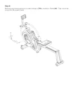
Page 18: ...Step 8 Before using the equipment connect Adaptor 79 to the Main Frame 10 Then insert the plug into the power socket...

Page 19: ...oot The below image shows the direction to loosen and tighten the strap Pedal Adjustment Remove the Pedal 21 from the Pedal Fixed Board 24 Pull it up and down as per your preference Insert the pedal h...

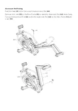
Page 20: ...Seat 31 to the front end of the Aluminium Rail 64 Remove the L bolt 59 on the Main Frame 10 to make the Aluminium Rail 64 rotate freely Turn up the Aluminium Rail 64 and fix the Aluminium Rail 64 on t...

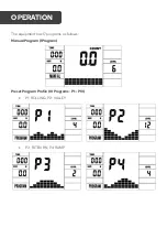
Page 21: ...The equipment has 17 programs as follows Manual Program 1 Program Preset Program Profile 10 Programs P1 P10 P1 ROLLING P2 VALLEY P3 FATBURN P4 RAMP OPERATION...

Page 22: ...P5 MOUNTAIN P6 INTERVAL P7 CARDIO P8 ENDURANCE P9 SLOPE P10 RALLY...

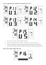
Page 23: ...TIME and WATT CAL and DIST at the same time 3 The computer will turn off automatically if there is no operation for more than 4 minutes It will store your current exercise data and run the loading res...

Page 24: ...he programs During any mode hold down this button for 2 seconds to totally reset the computer UP In the STOP mode press this button to select the program up When the related program window value is di...

Page 25: ...Control Program WATT PRO P16 o Press UP DOWN to select the watt control program o Press ENTER to confirm the selected watt control program and enter the time setting window o The time will flash and...

Page 26: ...cise Value Ranges Count Shows your current speed Range 0 0 999 count Rpm Shows the current rotate per minute Range 0 999 Time Shows the accumulative exercise time range 0 00 99M 59S The preset time ra...

Page 27: ...Adaptor Input Voltage AC 100 240V Output Power DC 9V 1A SPECIFICATIONS...

Page 28: ...ion We hope that this user guide has given you the assistance needed for a simple set up For the most up to date guide for your product as well as any additional assistance you may require head online...

Reviews: