


Changing FortiSwitch-5003B SW2 switch settings
Hardware installation
FortiSwitch-5003B System Guide
18
01-400-134822-20120216
http://docs.fortinet.com/
2
Remove the caps from SFP+ cage sockets on the FortiSwitch-5003B front panel.
3
Hold the sides of the SFP transceiver and slide SFP transceiver into the cage socket
until it clicks into place.
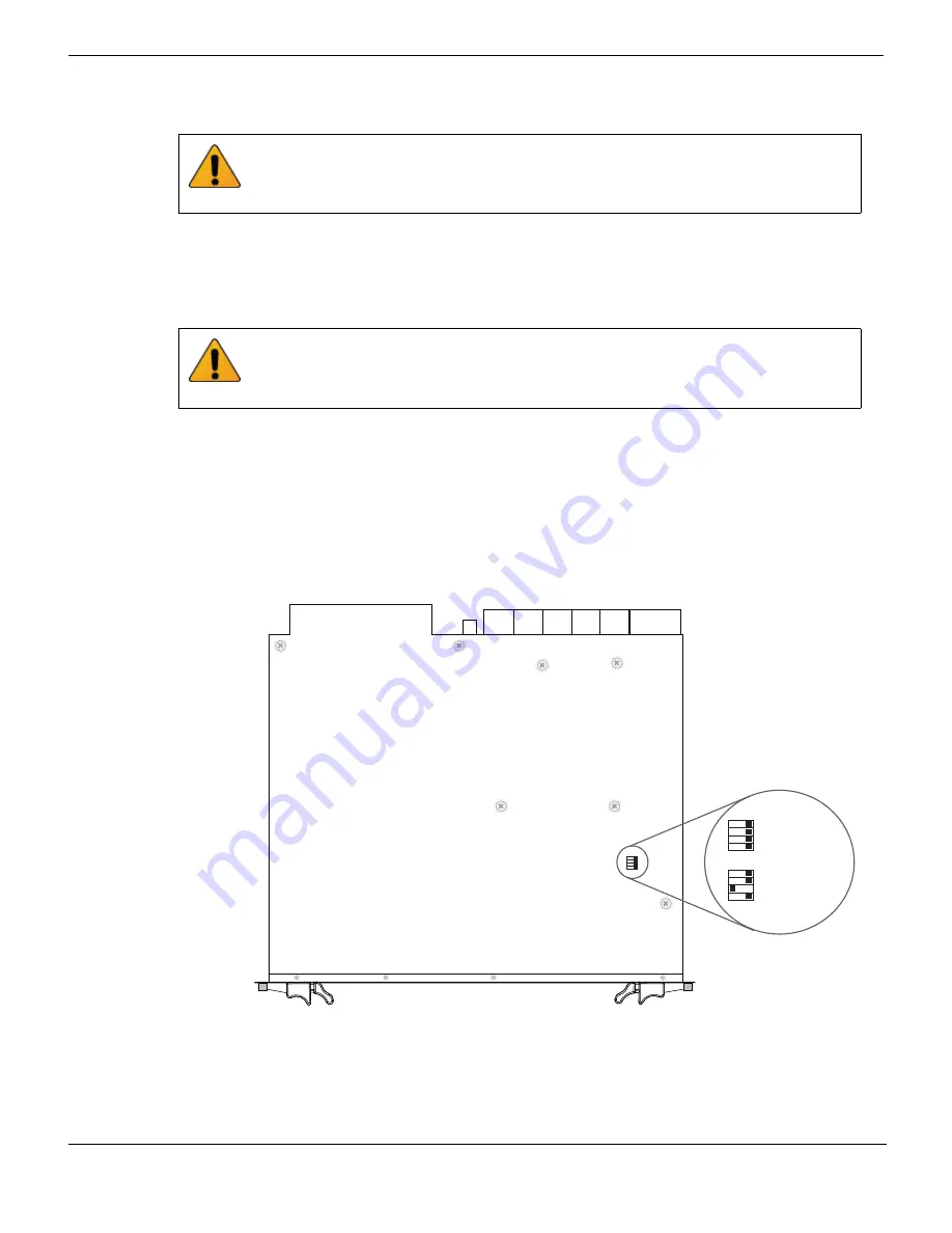
Changing FortiSwitch-5003B SW2 switch settings
The SW2 switch on the FortiSwitch-5003B board is factory set by Fortinet to detect a
shelf manager (
Figure 5
). This is the correct setting if you are installing the
FortiSwitch-5003B board in a chassis that contains an operating shelf manager (such as
a FortiGate-5000 series chassis).
The top of the FortiSwitch-5003B board is covered with a metal panel. The printed circuit
board is under the metal panel. SW2 is located on the printed circuit board and is
accessible through the small opening the metal panel as shown in
Figure 5
.
Figure 5: Location of SW2 on the FortiSwitch-5003B board
Handling the SFP+ transceivers by holding the release latch can damage the connector.
Do not force the SFP+ transceivers into the cage slots. If the transceiver does not easily
slide in and click into place, it may not be aligned correctly. If this happens, remove the
SFP+ transceiver, realign it and slide it in again.
You should only change the SW2 switch setting if are required to install the
FortiSwitch-5003B board in a chassis that does not contain a functioning shelf manager.
The default SW2 setting is required for most uses of the FortiSwitch-5003B including
ELBCv3.
FortiSwitch-5003B
Front Faceplate
Location of SW2
Factory Default
(Requires Shelf
Manager)
ON
SW2
34
2
1
ON
SW2
34
2
1
ON
SW2
34
2
1
Standalone Mode
(No Shelf Manager)


