


FortiGate-6000F hardware description
Fortinet Technologies Inc.
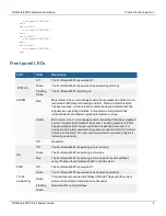
LED
State
Description
Off
No link is established.
25 to 28
Link/Activity
Green
This interface is connected at 100Gbps /40Gbps with the correct cable and
the attached network device has power.
Flashing
Green
Network traffic on this interface.
Off
No Link
MGMT1
MGMT2 Link/
Activity (Left
LED)
Green
This interface is connected at 1Gbps or 100Mbps with the correct cable
and the attached network device has power.
Flashing
Green
Network traffic on this interface.
Off
No link is established.
MGMT1
MGMT2
Speed (Right
LED)
Green
This interface is connected at 1Gbps.
Amber
This interface is connected at 100Mbps
Off
No link is established.
MGMT3 Link/
Activity (Left
LED)
Green
This interface is connected at 10Gbps or 1Gbps with the correct cable and
the attached network device has power.
Flashing
Green
Network activity at the interface.
Off
No link is established.
MGMT3
(Right LED)
Not used.
HA1 HA2
Link/Activity
Green
This interface is connected at 10Gbps or 1Gbps with the correct cable and
the attached network device has power
Flashing
Green
Network activity at the interface.
Off
No link is established.
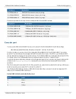
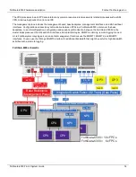
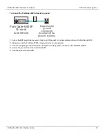
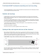
Front panel connectors
You connect the FortiGate-6000F to your 25 Gbps or 10 Gbps networks using the 1 to 24 SFP28 front panel interfaces.
You can also connect the FortiGate-6000F to your 100 Gbps or 40 Gbps networks using the 25 to 28 front panel
QSFP28 interfaces. The front panel also includes 10 GigE SPF+ HA heartbeat interfaces (HA1 and HA2), two Ethernet
10/100/1000 copper management interfaces (MGMT1 and MGMT2), a 10 GigE SPF+ management interface
(MGMT3), an RJ-45 RS-232 serial console port, and a USB port. The USB port can be used with any USB key for
backing up and restoring configuration files.
FortiGate-6000F 6.4.2 System Guide
9