Fortinet FIM-7904E Manual Download Page 5

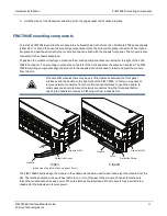
FIM-7904E interface module

Physical Description

l

One 1Gbps base backplane channel for base backplane with each FPM module installed in the same chassis as the
FIM-7904E.

l

One 40Gbps fabric backplane channel for fabric backplane communication with the other FIM-7904E in the chassis.

l

One 1Gbps base backplane channel for base backplane communication with the other FIM-7904E in the chassis.

l

On-board DP2 processors and an integrated switch fabric to provide high-capacity session-aware load balancing.

l

One front panel USB port.

l

Power button.

l

NMI switch (for troubleshooting as recommended by Fortinet Support).

l

Mounting hardware.

l

LED status indicators.

Physical Description

Dimensions

1.2 x 11.34 x 14 in. (3.1 x 28.8 x 35.1 cm) (Height x Width x Depth)

Weight

7.2 lb. (3.23 kg)

Operating Temperature

32 to 104°F (0 to 40°C)

Storage Temperature

-31 to 158°F (-35 to 70°C)

Relative Humidity

10% to 90% (Non-condensing)

Front panel LEDs

From the FIM-7904E font panel you can view the status of the module LEDs to verify that the module is
functioning normally.

LED

State

Description

 STATUS

Off

The FIM-7904E is powered off.

Green

The FIM-7904E is powered on and operating normally.

Flashing
Green

The FIM-7904E is starting up.

ALARM

Red

Major alarm.

Amber

Minor alarm

Off

No alarms

FIM-7904E Interface Module Guide
Fortinet Technologies Inc.

5

Summary of Contents for FIM-7904E

Page 1: ...FIM 7904E Interface Module Guide 7000...

Page 2: ...t com how to work with fortinet support FORTIGATE COOKBOOK http cookbook fortinet com FORTINET TRAINING SERVICES http www fortinet com training FORTIGUARD CENTER http www fortiguard com FORTICAST http...

Page 3: ...board from a chassis 16 Troubleshooting 18 FIM 7904E does not startup 19 FIM 7904E status LED is flashing during system operation 19 Quick FIM 7904E configuration 20 Registering your FortiGate 7000 se...

Page 4: ...ent Interface Status Alarm HA and Power LEDS USB Power Button NMI Button The FIM 7904E includes the following hardware features l Eight front panel 40GigE QSFP fabric channel interfaces B1 to B8 These...

Page 5: ...troubleshooting as recommended by Fortinet Support l Mounting hardware l LED status indicators Physical Description Dimensions 1 2 x 11 34 x 14 in 3 1 x 28 8 x 35 1 cm Height x Width x Depth Weight 7...

Page 6: ...Off No link is established M1 and M2 Green The correct cable is connected to the interface and the connected equipment has power Flashing Green Network activity at the interface Off No link is establi...

Page 7: ...on FG TRAN QSFP SR 40GE QSFP transceivers short range FG TRAN QSFP LR 40GE QSFP transceivers long range Breakout cables available from Fortinet for the FIM 7904E B1 to B8 QSFP interfaces Breakout Desc...

Page 8: ...t like any other FortiGate interface Turning the module on and off You can use the front panel power button to turn the module power on or off If the module is powered on press the power switch to tur...

Page 9: ...hitecture FIM 7904E hardware architecture Chassis Base Backplane Chassis Fabric Backplane CPU Integrated Switch Fabric Management MGMT1 4 Heartbeat M1 M2 Data B1 B8 DP2 DP2 DP2 1G 80G 40G FIM 7904E In...

Page 10: ...bps The M1 and M2 interfaces are used for heartbeat session sync and management communication between FIM 7904Es in different chassis This communication requires 10 Gbps connections so even though it...

Page 11: ...slot and are used to insert and eject the module from the slot On some FIM modules there may be very little clearance between the front panel interfaces and the handle on the right side of the FIM 79...

Page 12: ...ered on To insert a FIM 7904E into a chassis slot Do not carry the FIM 7904E by holding the handles or retention screws When inserting or removing the FIM 7904E from a chassis slot handle the module b...

Page 13: ...le FIM 7904E is being installed into chassis slot 1 of a FortiGate 7040E chassis 2 Unlock the left and right handles by pushing the handle latches up about 2 mm until the handles pop open Fully open b...

Page 14: ...e sliding the module in the module could be aligned incorrectly Pull the module back out and try inserting it again 4 Push both handles closed and close the latches Closing the handles draws the modul...

Page 15: ...s to be adjusted between 3 In lb to 4 In lb 0 4 N m to 0 48 N m As the latches are locked power is supplied to the module If the chassis is powered on during insertion the status LED flashes green as...

Page 16: ...ndles or retention screws When inserting or removing the FIM 7904E from a chassis slot handle the module by the front panel The handles are not designed for carrying the board If the handles become be...

Page 17: ...ust fully loosen the screws or the handles may be damaged when used to eject the board from the chassis slot 2 Unlock the left and right handles by pushing the latches up about 2 mm until the handles...

Page 18: ...oderate force to eject the module from the chassis 4 Hold the module front panel sides and slide it part way out of the slot Then grasp the module by the sides and carefully slide it out of the slot T...

Page 19: ...with FortiOS Connect to the FIM 7904E console and try cycling the power to the board If the BIOS starts up interrupt the BIOS startup and install a new firmware image If this does not solve the proble...

Page 20: ...oduct by visiting https support fortinet com To register enter your contact information and the serial numbers of the Fortinet products that you or your organization have purchased Choosing the config...

Page 21: ...and start over From the CLI enter execute factoryreset Connect to the GUI by connecting MGMT1 of the module in slot 1 to your network and browsing to https 192 168 1 99 Log into the GUI using the admi...

Page 22: ...sed Ventilation r duite Installation de l quipement dans un rack doit tre telle que la quantit de flux d air n cessaire au bon fonctionnement de l quipement n est pas compromise Mechanical Loading Mou...

Page 23: ...ent intended for installation in Restricted Access Location Avertissement Le mat riel est con u pour tre install dans un endroit o l acc s est restreint Warning A readily accessible disconnect device...

Page 24: ...green with yellow stripe conductor minimum size 6 AWG and the connection is to be installed by a qualified service personnel Ce produit a une borne de mise la terre s par sur le dos de l appareil en...

Page 25: ...residential area is likely to cause harmful interference in which case the user will be required to correct the interference at his own expense WARNING Any changes or modifications to this product not...

Page 26: ...gulatory Notices Voluntary Control Council for Interference VCCI Japan Product Safety Electrical Appliance Material PSE Japan PSE Bureau of Standards Metrology and Inspection BSMI Taiwan China A 26 FI...

Page 27: ...inet enters a binding written contract signed by Fortinet s General Counsel with a purchaser that expressly warrants that the identified product will perform according to certain expressly identified...

Reviews: