18
WWW.FORNEYIND.COM
be adjusted to match the wire feed speed/welding current. Progressively select higher voltage positions when
increasing wire speed.
Increasing welding voltage leads to a longer arc (without substantially affecting the current). Conversely, a
decreased welding voltage results in a shorter arc (the current again is not substantially changed). A change in wire
diameter results in changed parameters. A larger diameter wire will draw a higher current than a smaller diameter
wire at the same wire feed speed. If certain limits are exceeded, a satisfactory weld cannot be obtained. These are:
1.
Feeding wire too fast (too high speed with regard to the welding voltage) results in pulsing within the gun. This
is because the wire electrode dips into the puddle and cannot be melted off fast enough.
2.
Setting welding voltage too high (too high with regard to the wire feed speed), will result in excessive and
unstable arc. Increase the voltage even higher and the contact tip will burn.
3.
Excessive wire speed can be corrected through the arc voltage increase. The limit of this adjustment depends on
the thickness of the material to be welded (a certain limit exceeded will result in burn through).
Place the gun on the joint you want to weld: the angle between the gun and the workpiece should be around 45°.
The distance between the gun and the workpiece should be about 1/2” - 5/8”. Lower your face shield and press
the gun trigger to start the arc. When the arc has struck, move the nozzle slowly from left to right along the joint.
Adjust the wire feed speed until the arc makes a “crisp” sound (experience will help you to recognize the right
sound).
• Ensure the ground clamp has a good connection to the workpiece and is connected on clean, bare metal (not
rusty or painted).
• Ensure the ground clamp has a good connection to the workpiece and is connected on clean, bare metal (not
rusty or painted).
• Load the spool of wire inside the cabinet and feed it through the WIRE FEEDER (11) into the gun (see “Installing
the Welding Wire”, page 14).
• Switch the unit ON with the ON/OFF SWITCH (8).
• Press the gun trigger to load the wire through the gun.
• Set the welding parameters:
1. Adjust wire feed speed with the RIGHT KNOB (5).
2. Adjust arc voltage with the LEFT KNOB (4).
• Touch the end of the electrode wire to the workpiece and depress the gun trigger completely. The arc will initiate
and wire will begin to feed.
NOTE:
The gun for your machine includes a micro-switch trigger. This provides greater trigger reliability than
typical guns, but requires the trigger to be depressed completely to make contact. Failure to depress the trigger
completely may result in erratic arc starting and stopping.
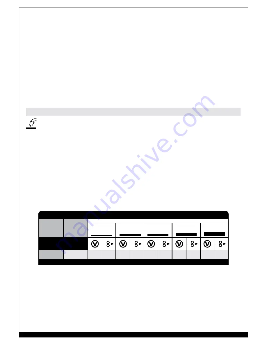
Regulation Knob
Mild Steel
.030” (0.8 mm)
E71T-GS
1
2
4
4
7
7
9
9
10
10
CANNOT WELD ALUMINUM
MATERIAL
(Wire)
WIRE
ø
MATERIAL THICKNESS
22 Gauge
.030” (0.8 mm)
16 Gauge
1/16” (1.6 mm)
1/8” (3 mm)
3/16” (5 mm)
1/4” (6 mm)
140 FC-i FCAW SET-UP CHART
Welding Tips:
• Always weld clean, dry and well-prepared material.
• Hold gun at a 45° angle to the workpiece with nozzle about 1/2” from the surface.
• Move the gun smoothly and steadily as you weld.
• On thin gauge material, move quickly and only weld 1/4” stitch-welds at a time to avoid melt-through.
• Avoid welding in very drafty areas. A weak, pitted and porous weld will result due to drafts blowing away the
protective welding gas.
• Keep wire and liner clean. Do not use rusty wire.
• Sharp bends or kinks in the welding cable should be avoided.
Setup for Flux-Cored Wire (FCAW) Welding


