www.forenex.com.tw
- 1 -
FR-E2Sxy
Ethernet to Serial interface
Reference Manual (Preliminary)
Version: 0.4.2
benson
Lon
Yu
Approved By
Checked By
Prepared By
***The content of this document is subject to be change without notice.***
Page 1: ...nex com tw 1 FR E2Sxy Ethernet to Serial interface Reference Manual Preliminary Version 0 4 2 benson Lon Yu Approved By Checked By Prepared By The content of this document is subject to be change without notice ...
Page 2: ...of revision Version Revise Date Page Description 0 1 0 3 5 0 4 0 0 4 1 0 4 2 2014 11 28 2014 12 24 2014 12 31 2015 1 8 2015 05 18 First issue For PCB revision 2 0 Added description about ETH to SPI Modified E g 1 and E g 2 of A 1 ...
Page 3: ...nnect to RS 232 UART TTL device 5 4 Connect to RS 232 UART TTL device with flow control 5 5 Connect to RS 485 device 5 6 Connect to SPI slave device 6 Remote Configuration over Web Page 12 6 1 The first time to configure E2S board 6 2 Detail of Web Page 7 Ethernet Application Examples 17 7 1 Connect to the Host via Ethernet cable directly 7 2 Connect to the Host via LAN 7 3 Implement existing seri...
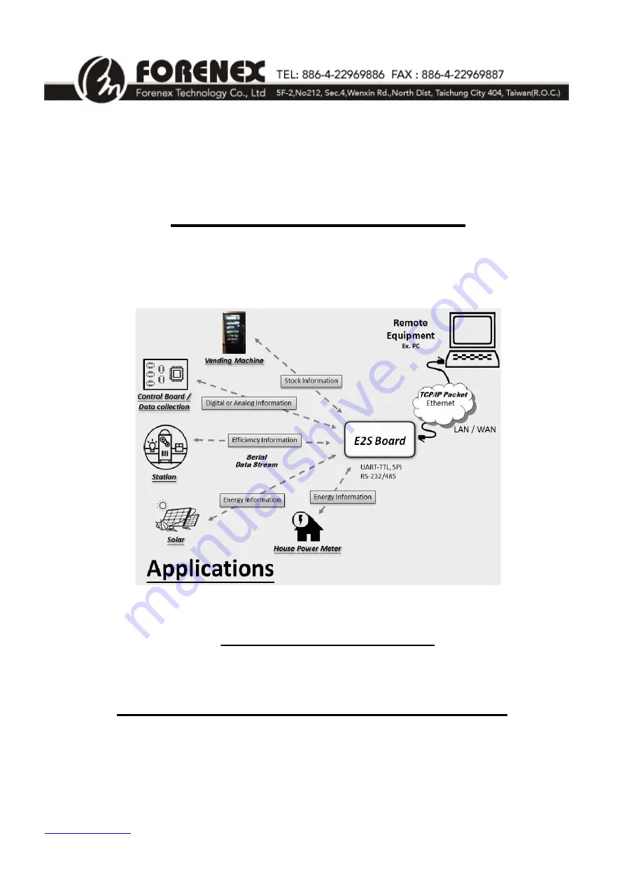
Page 4: ... RS 232 RS 485 UART TTL or SPI depends on the different E2S model On the other hand E2S is also to translate the data stream from a serial to TCP IP packet It provides an easier way to connect Ethernet by DHCP client or DNS client Besides a customized web page can configure E2S for an adaptive setting 1 2 System Architecture Figure 1 System Architecture 1 3 Ordering Information Part number FR E2S ...
Page 5: ... 6 Remote Configuration over Web Page z E2S UF UI model E2S RF RI model 1 UART TTL RS 232 signals 5 wire TX RX CTS RTS GND or 3 wire TX RX GND 2 Flow control functions None Hardware CTS RTS Software Xon Xoff 3 Baud Rate UART_TTL Support up to 921600 bps RS232 Support up to 115200 bps z E2S SF SI model 1 RS 485 signals 2 wire A Y B Z 2 Automatically enable control for the transmitter receiver of RS...
Page 6: ...nt UART TTL E2S UF UI model Baudrate 1200 921600 bps In 15 V out 5 5 5 V RS 232 signal level E2S RF RI model Baudrate 1200 115200 bps Note 1 In 15 V out 5V V RS 485 signal level E2S SF SI model Baudrate 1200 115200 bps Note 2 In out 3 3 V 5V tolerant SPI Interface E2S PF PI model Frequency 200K 1M Hz 0 80 ºC Commercial Operation Temperature 25 80 ºC Industrial Storage Temperature 40 130 ºC Note 1 ...
Page 7: ...www forenex com tw 7 4 Overview Dimension 4 1 Dimension 67mm L 40mm W Max 19 5mm H Unit mm Figure 2 Dimension Diagram ...
Page 8: ...mm H1 Serial signals connector Box Header 2x5 pin 2 0mm DIP Straight J1 Ethernet connector RJ 45 4 3 LED Status Name Status Description Light Ethernet was already linked Dark Ethernet is not connected Link LED Blinking When Ethernet is in receiving or transmitting state Light Ethernet work in 100BASE TX mode Speed LED Dark Ethernet work in 10BASE T mode Light Ethernet work in Full duplex mode Full...
Page 9: ...communications Box Header 2x5 pin 2 0mm Straight entry Top View Pin 1 3 5 7 9 Pin 2 4 6 8 10 H1 For E2S UF UI UART TTL and E2S RF RI RS 232 Pin No Signal I O Description 1 GND P Ground 2 RX I Receive Data form external Device 3 TX O Transmitte Data to external Device 4 5 GND P Ground 6 7 RTS O Request To Send 8 CTS I Clear to send 9 DC IN P External DC input as same as W1 10 DC IN P External DC in...
Page 10: ... External DC input as same as W1 10 DC IN P External DC input as same as W1 For E2S PF PI SPI Pin No Signal I O Description 1 GND P Ground 2 MISO I Receive Data form external Device 3 MOSI O Transmitte Data to external Device 4 5 GND P Ground 6 7 SCLK O SPI Clock output 8 nSS O Slave Select output Active low 9 DC IN P External DC input as same as W1 10 DC IN P External DC input as same as W1 ...
Page 11: ...RS 232 UART TTL device 5 4 The E2S RF RI connects to RS 232 device with flow control The E2S UF UI connects to UART TTL device with flow control Figure 5 Connect to 5 wire RS 232 UART TTL device 5 5 The E2S SF SI connects to RS 485 device Figure 6 Connect to RS 485 device 5 6 The E2S PF PI connects to SPI slave device Figure 7 Connect to SPI slave device ...
Page 12: ...has default at 192 168 0 3 therefore make sure the IP address of host PC sets as same segment as 192 168 0 xxx xxx is between 1 and 254 except 3 a PC connects to E2S board directly b The E2S board connects to LAN 6 2 Authentication page Open a web browser and enter http 192 168 0 3 When the login window appears set the user name to admin and set the password to admin Click Login to continue Figure...
Page 13: ...www forenex com tw 13 6 3 Basic Page This page can change Serial settings and Ethernet settings for E2S Figure 9 Basic settings page ...
Page 14: ...op Bits 1 1 1 5 2 Flow Control None Xon Xoff Hardware None For SPI Settings Features Default All option Data Baud Rate 250KHz 1MHz 750KHz 500KHz 400KHz 250KHz 200KHz SPI Mode 0 0 1 2 3 Differences between the SPI Mode 0 3 MSB D6 D5 D4 D3 D2 D1 LSB MOSI CPOL 0 CPHA 0 Capture SCLK Rising Edge SCLK Inactive Low Level CPOL 1 CPHA 1 Capture SCLK Rising Edge SCLK Inactive High Level CPOL 0 CPHA 1 Captur...
Page 15: ...Port under Server mode The default value is 5000 Please enter an integer between 1024 65535 Destination Host Name IP under Client mode The default value is 192 168 0 2 Note 2 Can accept either host name or IP address format e q you can enter forenex com tw or 192 168 0 2 in this field Destination Port under Client mode The default value is 5000 Note 2 Please enter an integer between 1024 65535 Dis...
Page 16: ...urity page Attentions The Accessible IP Setting group must be used carefully Once set these four IP list and be enabled E2S board can only be configured by these four IP address over Web page When you change the accessible IP successful you must reboot device to take it effect Please confirm settings before reboot device ...
Page 17: ...be set to 192 168 0 xxx xxx is between 1 and 254 except 3 d When E2S is working in Client mode the setting of Destination Host Name IP must as same as Host IP and the setting of Destination Host Port must as same as listen port of Host Then Host need to wait for the E2S to establish a TCP UDP connection e When E2S is working in Server mode the setting of Listening Port is the port provide for Host...
Page 18: ...able for a valid IP asking b If E2S works in Server mode and DHCP client is enabled Host has to check the IP of E2S before establish a TCP UDP connection c Following up the 7 1 c d and e section Figure 13 Working in Client mode to connect the Host via LAN Figure 14 Working in Server mode to connect the Host via LAN ...
Page 19: ...E2S 2 and Destination Port on E2S 1 must be the same Figure 15 Implement existing serial communications via Ethernet cable directly 7 4 Implement existing serial communications via LAN a Both IP of E2S 1 and E2S 2 should be different but in the same IP segment b As shown in figure11 E2S 1 set to client mode and E2S 2 set to server mode c The setting of Listening Port on E2S 2 and Destination Port ...
Page 20: ...case the E2S can only be worked under Client mode b This setting of Destination Host Name IP must as same as the remote server IP or server name c Remote server need to listen the listen port of E2S for wait a TCP UDP connection Figure 17 Connect to Remote Server via INTERNET ...
Page 21: ...ORTANT The description of Appendix A is only available for below models E2S UF UI UART TTL E2S RF RI RS 232 and E2S SF SI RS 485 When you enable Flow Control Packet at Web page setting you must follow below Data format or Command format to transmit receive Ethernet packet ...
Page 22: ...04 05 06 Length 0x06 6 bytes 01 02 03 04 05 06 Serial Target will get the 6 bytes from RS232 E g 2 Transmit data stream from RS232 to Ethernet Transmitted the leading bytes of data packet 32 01 38 Bytes Data Length 0x138 hexadecimal 312 Decimal bytes Serial Target should continue to send 312 bytes data after the leading bytes 32 01 38 were sent from RS232 A 2 Command format of Packet for flow cont...
Page 23: ...3 CLR_RTS 0x12 To clear RTS signal of RS232 and get result feedback with a 0x81 packet SET_RTS 0x14 To set RTS signal of RS232 and get result feedback with a 0x81 packet A 3 1 Command E2S_STATUS_CHANGE 0x81 Item Description OP1 Bit 0 Delta Clear To Send indicator 1 The CTS line has changed its state Bit 4 Complement of the CTS input 1 CTS was input logic 0 0 CTS was input logic 1 OP2 Bit 1 Request...
Page 24: ... GET_E2S_STATUS 0x03 Item Description OP1 Bit 0 Delta Clear To Send indicator 1 The CTS line has changed its state Bit 4 Complement of the CTS input 1 CTS was input logic 0 0 CTS was input logic 1 A 3 3 Command CLR_RTS 0x12 SET_RTS 0x14 ...
Page 25: ... from E2S A 1 Write data to SPI Slave device 1 Packet format shall refer to protocol of SPI Slave Device 2 When E2S received any packet form Ethernet The E2S will assert a completed SPI transition cycle that base on the protocol of SPI Slave Device And bypass entire packet to SPI Slave device without change 3 When Host received a return packet from E2S that means the previous packet has been perfo...
Page 26: ...rotocol of SPI Slave Device And bypass entire packet to SPI Slave device without change 3 The return data packet includes invalid and valid data The valid data will be located as same as the dummy bytes which have been defined in packet E g If you want to read 4 Bytes data form AMIC A25LQ64 The packet form Host should be 1 Byte Command 3 Bytes Address 4 Bytes Dummy When single packet processing is...