Ford 2006 Escape J87R Bodyshop Manual Download Page 73

BODY STRUCTURE [DIMENSIONS]

09-80D–5

80D

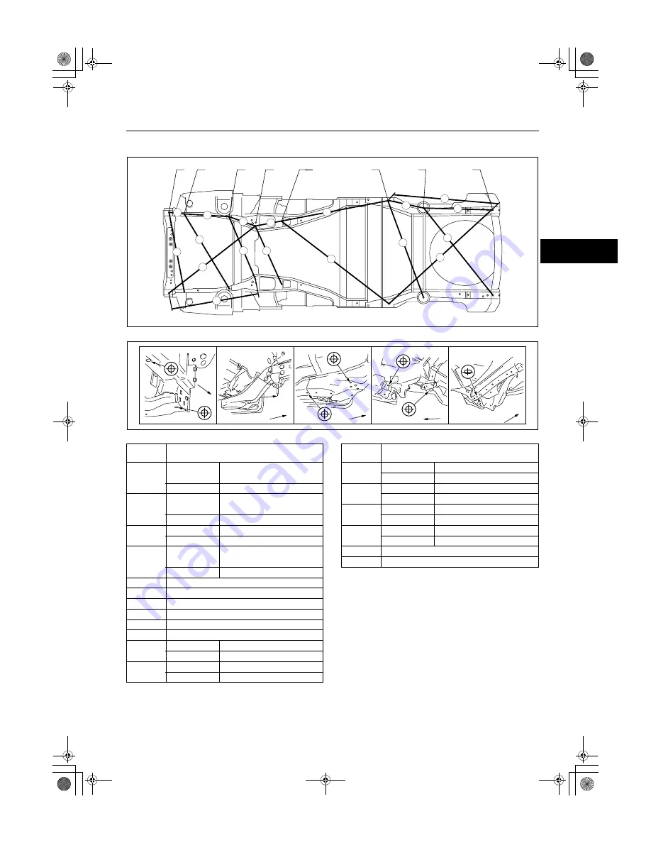
UNDERBODY STRAIGHT-LINE DIMENSIONS[DIMENSIONS]

id098010740500

.

End Of Sie

BM: FRONT BODY

A

B

D

E

F

G

I

J

9

8

7

5

4

3

1

2

6

18

17

15

16

14

13

11

12

10

BUE0980B043

G,I

G

E

A

B

F

I

A,B

D

E,F

J

Fr

Fr

Fr

Fr

Fr

BUE0980B044

Measured 

location

Dimensions mm {in}

1

R.H.D. models

RH:214 {8.42},

LH:215 {8.46}

L.H.D. models

 156 {6.14}

2

R.H.D. models

RH:1,023 {40.27},

LH:1,032 {40.62}

L.H.D. models

1,037 {40.83}

3

R.H.D. models

558 {21.96}

L.H.D. models

628 {24.72}

4

R.H.D. models

RH:1,105 {43.50},

LH:1,096 {43.14}

L.H.D. models

1,154 {45.43}

5

1,357 {53.42}

6

1,063 {41.85}

7

345 {13.58}

8

867 {34.15}

9

430 {16.94}

10

859 {33.82}

11

R.H.D. models

1,262 {49.68}

L.H.D. models

1,264 {49.77}

12

R.H.D. models

1,602 {63.07}

L.H.D. models

1,612 {63.46}

13

R.H.D. models

425 {16.73}

L.H.D. models

428 {16.85}

14

R.H.D. models

1,229 {48.38}

L.H.D. models

1,243 {48.94}

15

R.H.D. models

1,144 {45.03}

L.H.D. models

1,145 {45.08}

16

R.H.D. models

1,613 {63.50}

L.H.D. models

1,623 {63.91}

17

721 {28.39}

18

1,294 {50.94}

Measured 

location

Dimensions mm {in}

Summary of Contents for 2006 Escape J87R

Page 1: ......

Page 2: ...nual are effective methods of performing service and repair Some require tools specifically designed for a specific purpose Persons using procedures and tools which are not recommended by Ford Motor C...

Page 3: ...ume will be made available at Ford dealers This manual should be kept up to date Ford Motor Company reserves the right to alter the specifications and contents of this manual without obligation or adv...

Page 4: ......

Page 5: ...Of Sie VEHICLE IDENTIFICATION NUMBERS VIN id000000600100 LFA CKZTNX 2 000001 LFA CLZTNX 2 000001 LFA CMZTVX 2 000001 LFA CNZTVX 2 000001 LFA YKZTNX 2 000001 LFA YLZTNX 2 000001 LFA YMZTVX 2 000001 LFA...

Page 6: ...lacing body panels REAR FENDER PANEL REMOVAL Shows operation section Shows procedure caution and note BRAZE WELDING CUT AND JOINT LOCATION CUT AND JOINT LOCATION ROUGH CUT LOCATION ROUGH CUT LOCATION...

Page 7: ...plane surface When there are no specific indications the standard points and dimensions are symmetrical in regard to the center of the vehicle The hypothetical lines may differ according to the vehic...

Page 8: ...e Link bracket Rear suspension housing A B C D E F G H I J K Rear side frame standard hole Rear side frame standard hole Shows bolt size Shows hole diameter Shows slot mm in UNDERBODY FLAT PLANE DIMEN...

Page 9: ...n Shows outline drawing C D A G Shows point symbol Shows point indication Without apostrophe RH With apostrophe LH Shows details of the standard point location Shows position and shape of the points S...

Page 10: ...d floor covers Use heat resistant protective covers to protect glass areas and seats from heat or sparks during welding Protect items such as moldings garnishes and ornaments with tape when welding Re...

Page 11: ...Securely connect the welding machine ground near the welding area End Of Sie EFFICIENT REMOVAL OF BODY PANELS id000000600300 Body Measurements Before removal or rough cutting first measure the body a...

Page 12: ...cement the selected cutting location should be where the welding distortion will be minimal Removal of Associated Parts Protect moldings garnishes and ornaments with tape when removing associated part...

Page 13: ...not be spot welded make a hole for CO2 arc welding using a punch or drill as follows mm in Grind the shaded section indicated in the diagram below and create a hole in the part where the 3 4 plates ar...

Page 14: ...nts And Watching Align to the standard reference dimensions based upon the body dimensions illustration so that new parts are installed in the correct position Welding Notes For the number of weld poi...

Page 15: ...eld strength is affected by the shape of the spot welder tip the optimum condition of the tip should always be maintained Spot welds should be made at points other than the originally welded points Be...

Page 16: ...tween the panels according to the number of panels as shown below To determine weld strength drive the chisel between the panel and check whether the panels come apart If the panels come apart make an...

Page 17: ...s difficult after installation apply it before installation Application of Undercoating Apply an undercoat to the required location of the body Application of Rust Inhibitor Apply rust inhibitor wax o...

Page 18: ...00 00 14 GENERAL INFORMATION ABBREVIATION id000000600700 End Of Sie CM Control module Ctr Center DSC Dynamic stability control Fr Front HU Hydraulic unit LH Left M Metallic MC Mica RH Right Rr Rear...

Page 19: ...80B BODY STRUCTURE WATER PROOF AND RUST PREVENTIVE 09 80C BODY STRUCTURE DIMENSIONS 09 80D BODY STRUCTURE PLASTIC BODY PARTS 09 80E BODY STRUCTURE PRIMARY COLOR MIXTURE CHART FOR BODY COLOS 09 80F To...

Page 20: ...ONSTRUCTION CONSTRUCTION id098007739700 R H D MODELS 9 8 7 5 4 3 1 2 10 6 19 18 17 15 16 14 13 11 12 20 28 27 29 25 26 24 23 21 22 30 39 38 37 35 36 34 33 31 32 40 63 62 61 60 58 59 64 65 47 45 46 44...

Page 21: ...30 0 091 20 Dash lower panel 0 75 0 030 21 Cowl upper plate x x 1 20 0 047 22 Dash upper panel 0 70 0 028 23 Cowl panel x 0 70 0 028 24 Torque box reinforcement x 1 20 0 047 25 Cowl side reinforcemen...

Page 22: ...5 Front floor pan 0 80 0 031 56 Crossmember No 2 5 0 80 0 031 57 Crossmember No 3 upper 0 80 0 031 58 Seat bracket 0 70 0 028 59 Rear side frame x x 1 40 0 055 60 Hook bracket x x 1 20 0 047 61 Wheel...

Page 23: ...9 80A 5 80A L H D MODELS 9 8 7 5 4 3 1 2 10 6 19 18 17 15 16 14 13 11 12 20 28 27 29 25 26 24 23 21 22 30 39 38 37 35 36 34 33 31 32 40 63 62 61 60 58 59 64 66 47 45 46 44 43 41 42 48 65 57 56 55 53 5...

Page 24: ...ate x x 1 20 0 047 22 Dash upper panel x 0 70 0 028 23 Cowl panel x 0 70 0 028 24 Torque box reinforcement x 1 20 0 047 25 Cowl side reinforcement 1 40 0 055 26 Cowl side panel x 0 70 0 028 27 Hinge p...

Page 25: ...0 0 031 57 Crossmember No 3 upper 0 80 0 031 58 Seat bracket 0 70 0 028 59 Rear side frame x x 1 40 0 055 60 Hook bracket x x 1 20 0 047 61 Wheel house panel x 0 70 0 028 62 Rear floor pan x 0 65 0 02...

Page 26: ......

Page 27: ...INSTALLATION PANEL REPLACEMENT 09 80B 13 FRONT PILLAR REMOVAL PANEL REPLACEMENT 09 80B 14 FRONT PILLAR INSTALLATION PANEL REPLACEMENT 09 80B 16 CENTER PILLAR REMOVAL PANEL REPLACEMENT 09 80B 18 CENTE...

Page 28: ...ions C End Of Sie RADIATOR SHROUD PANEL COMPONENT INSTALLATION PANEL REPLACEMENT id098008614600 1 When installing new parts position each part so that the section measurement aligns with the body dime...

Page 29: ...r No 1 End Of Sie CROSSMEMBER No 1 INSTALLATION PANEL REPLACEMENT id098008603600 1 When installing new parts position each part so that the section measurement aligns to the body dimension 2 Drill hol...

Page 30: ...reful not to damage the windshield when drilling the 2 locations indicated by A 3 Remove the apron reinforcement front Note Drilling of the 5 locations indicated by B is not necessary when replacing t...

Page 31: ...s before installing new parts 3 Install in the following order apron reinforcement front cowl side reinforcement front and cowl side reinforcement rear and apron reinforcement 4 After temporarily inst...

Page 32: ...1 Drill the 59 weld locations indicated by A and remove the wheel apron panel component Note When removing the wheel apron panel front and the suspension housing separately drill 14 locations indicate...

Page 33: ...ds before installing new parts 3 Plug welding of 7 weld locations indicated by A during installation of the cowl side reinforcement 4 After temporarily installing new parts make sure the related parts...

Page 34: ...interfere with the front frame rear and make removal difficult Therefore drill 11 locations indicated by A then open the front frame rear outward 2 Drill the 3 weld locations indicated by B from the...

Page 35: ...LACEMENT id098008742000 1 When installing new parts position each part so that the section measurement aligns to the body dimension 2 After temporarily installing new parts make sure the related parts...

Page 36: ...f the outer drill the 3 weld locations indicated by A and bend the wheel apron panel front upward 2 Rough cut at the locations shown in the figure to remove damaged parts End Of Sie A 3 150mm 5 90in 1...

Page 37: ...rts 5 Install the hook reinforcement and the frame reinforcement before installing the outer 6 Because the outer cannot be welded to the old parts from the inside of the frame drill 2 plug weld holes...

Page 38: ...d by B and 12 RH and 11 LH weld locations indicated by C from the room side Note The weld locations A B and C in the figure indicate the same locations 2 Drill the 2 weld locations indicated by D from...

Page 39: ...easurement aligns to the body dimension 2 Drill holes for plug welds before installing new parts 3 Plug welding of 2 weld location indicated by E during installation of the front side frame 4 After te...

Page 40: ...he 31 locations indicated by E is not necessary when removing the front pillar and the front pillar inner at the same time If the side sill reinforcement is not damaged do not dispose of it as it can...

Page 41: ...PANEL REPLACEMENT 09 80B 15 80B End Of Sie C 6 D 4 C 2 C 6 INSULATOR 90mm 3 54in 130mm 5 11in C ROUGH CUT LOCATION FOR THE SIDE SILL REINFORCEMENT ROUGH CUT LOCATION FOR THE FRONT PILLAR REINFORCEMEN...

Page 42: ...ll holes for plug welds before installing new parts Note In areas where the outer reinforcement inner and other parts are in 3 4 layers drill holes for plug welds in all but the innermost panel 3 Afte...

Page 43: ...1 96in 50mm 80mm 3 15in 50mm 1 96in 90mm 3 54in CUT AND JOIN LOCATION FOR THE FRONT PILLAR REINFORCEMENT CUT AND JOIN LOCATION FOR THE SIDE SILL REINFORCEMENT CUT AND JOIN LOCATION FOR THE FRONT PILLA...

Page 44: ...ged considerably replace it with a new one 3 Drill the 19 locations indicated by D and remove the center pillar End Of Sie 11 4 3 D 9 B 13 BOTTOM SIDE B 3 B 3 B 8 B 9 D 6 B 2 D 2 D 2 5 A A B B C C A A...

Page 45: ...After installing and temporarily install the inner reinforcement and the side sill reinforcement plug weld during installation of the outer 4 After temporarily installing new parts make sure the relat...

Page 46: ...as the insulator shaded area is flammable 2 Remove the side sill reinforcement End Of Sie 14 10 30 17 20 B C C B A A 8 BOTTOM SIDE 3 3 3 2 6 3 SIDE SILL REINFORCEMENT A A B B C C INSULATOR INSULATOR...

Page 47: ...the standard dimensions 2 Drill holes for plug welds before installing new parts 3 Plug the 38 weld locations indicated by A during installation of the side sill reinforcement 4 After temporarily ins...

Page 48: ...llar inner are joined with glue at the wheel arch line Use a chisel or similar tool to separate the rear fender panel from the rear pillar inner then remove the rear fender panel End Of Sie INSULATOR...

Page 49: ...ust the position to align it to the standard dimensions 2 Drill holes for plug welds before installing new parts 3 Before installing new parts apply spot weld sealer to the wheel arch line 4 After tem...

Page 50: ...Remove the rear end panel 2 Remove the rear end side member 3 Remove the bumper bracket drill each weld location and remove the crossmember No 5 while pulling it from above End Of Sie 2 3 3 5 4 1 1 2...

Page 51: ...arts 3 Remove the bumper bracket from the crossmember No 5 and install the crossmember No 5 by inserting it from above 4 Install the bumper bracket and the rear end side member to the crossmember No 5...

Page 52: ...forcement Caution Avoid cutting with a blowtorch or similar tools as the insulator shaded area is flammable 3 Remove the corner plate End Of Sie 1 5 4 7 7 5 5 3 3 2 4 10 2 9 CORNER PLATE INNER SIDE 2...

Page 53: ...ew parts 3 Install in the following order corner plate rear pillar reinforcement and rear pillar outer 4 Weld locations indicated by A during installation of the rear pillar outer 5 Weld locations ind...

Page 54: ...d098008742700 1 Remove the rear floor pan Caution During rough cutting be careful not to damage the seat bracket indicated by dotted lines in the figure End Of Sie 9 14 22 100mm 3 93in A A ROUGH CUT L...

Page 55: ...nstalling new parts 2 Apply body sealer to the joints of old and new parts for waterproofing and rust protection 3 After temporarily installing new parts make sure the related parts fit properly End O...

Page 56: ...old parts at the cut and join location and bevel the parts 2 When installing the new parts position each part so that the section measurement aligns to the standard dimensions 3 After temporarily inst...

Page 57: ...BODY STRUCTURE PANEL REPLACEMENT 09 80B 31 80B ROOF PANEL REMOVAL PANEL REPLACEMENT id098008744300 1 Remove the roof panel End Of Sie 23 35 35 2 2 21 BRAZE WELDING BUE0980B034...

Page 58: ...NEL INSTALLATION PANEL REPLACEMENT id098008744400 1 Drill holes for plug welds before installing new parts 2 After temporarily installing new parts make sure the related parts fit properly End Of Sie...

Page 59: ...C 09 80C BODY STRUCTURE WATER PROOF AND RUST PREVENTIVE BODY SEALING WATER PROOF AND RUST PREVENTIVE 09 80C 2 UNDER COATING WATER PROOF AND RUST PREVENTIVE 09 80C 7 RUST PREVENTIVE TREATMENT WATER PRO...

Page 60: ...ENTIVE BODY SEALING WATER PROOF AND RUST PREVENTIVE id098009739800 Sealant is applied to the parts where the panels meet and to the hemmed parts of the door panel and bonnet panel to provide water pro...

Page 61: ...BODY STRUCTURE WATER PROOF AND RUST PREVENTIVE 09 80C 3 80C BUE0980B037...

Page 62: ...09 80C 4 BODY STRUCTURE WATER PROOF AND RUST PREVENTIVE BONNET DOOR LIFTGATE BUE0980B038...

Page 63: ...BODY STRUCTURE WATER PROOF AND RUST PREVENTIVE 09 80C 5 80C L H D models BUE0980B071...

Page 64: ...09 80C 6 BODY STRUCTURE WATER PROOF AND RUST PREVENTIVE End Of Sie BUE0980B072...

Page 65: ...PROOF AND RUST PREVENTIVE 09 80C 7 80C UNDER COATING WATER PROOF AND RUST PREVENTIVE id098009739900 The shaded areas indicated under body locations that are underacted to prevent noise and rusting R H...

Page 66: ...09 80C 8 BODY STRUCTURE WATER PROOF AND RUST PREVENTIVE L H D models End Of Sie BUE0980B073...

Page 67: ...VENTIVE 09 80C 9 80C RUST PREVENTIVE TREATMENT WATER PROOF AND RUST PREVENTIVE id098009740100 The carting locations are indicated by the shaded areas R H D models Rust prventive oil is not applied on...

Page 68: ......

Page 69: ...80D 5 FRONT BODY STRAIGHT LINE DIMENSIONS 1 DIMENSIONS 09 80D 6 FRONT BODY STRAIGHT LINE DIMENSIONS 2 DIMENSIONS 09 80D 7 CABIN SIDE FRAME STRAIGHT LINE DIMENSIONS DIMENSIONS 09 80D 8 ROOM STRAIGHT L...

Page 70: ...27 17 31 50 19 09 485 mm in BUE0980B042 Point symbol Designation Hole diameter or bolt size or nut size mm in A Crossmember No 1 standard hole 16 0 62 B Front side frame standard hole 16 0 62 C Front...

Page 71: ...symbol Designation Hole diameter or bolt size or nut size mm in A Crossmember No 1 standard hole 16 0 62 B Front side frame standard hole 19 25 0 75 0 98 C Front suspension mounting block surface hole...

Page 72: ...09 80D 4 BODY STRUCTURE DIMENSIONS L H D Face lifted model End Of Sie 153 54 3 900 394 15 51 1 034 40 71 1 250 49 21 780 738 1 020 40 16 30 71 29 06 mm in CUE0980B151...

Page 73: ...H D models 1 037 40 83 3 R H D models 558 21 96 L H D models 628 24 72 4 R H D models RH 1 105 43 50 LH 1 096 43 14 L H D models 1 154 45 43 5 1 357 53 42 6 1 063 41 85 7 345 13 58 8 867 34 15 9 430...

Page 74: ...location Dimensions mm in 1 1 114 43 87 2 R H D models 647 25 47 L H D models 644 25 36 3 R H D models 1 433 56 41 L H D models 1 432 56 38 4 1 468 57 79 5 1 544 60 79 6 1 080 42 52 7 1 082 42 60 8 R...

Page 75: ...12 BUE0980B047 F D A B C A B C D E Fr Fr Fr Fr BUE0980B048 Measured location Dimensions mm in 1 1 410 55 51 2 1 438 56 61 3 1 079 42 48 4 1 428 56 22 5 1 370 53 94 6 69 2 74 7 1 426 56 14 8 349 13 74...

Page 76: ...D E A B C Fr Fr Fr Fr Fr Fr K H F I G F I G H J Fr Fr Fr BUE0980B050 Measured location Dimensions mm in 1 864 34 01 2 921 36 25 3 1 272 50 07 4 1 169 46 02 5 591 23 26 6 765 30 11 7 993 39 09 8 1 163...

Page 77: ...0980B075 D E F A B C Fr Fr Fr Fr Fr F E G H I Fr Fr Fr BUE0980B076 Measured location Dimensions mm in 1 868 34 17 2 925 36 42 3 1 275 50 20 4 1 171 46 10 5 1 039 40 91 6 1 062 41 81 7 1 097 43 19 8 1...

Page 78: ...H Fr Fr Fr Fr BUE0980B052 Measured location Dimensions mm in 1 1 180 46 47 2 1 114 43 86 3 852 33 55 4 1 299 51 14 5 R H D models 978 38 50 L H D models 942 37 09 6 754 29 70 7 RH 1 107 43 60 LH 1 162...

Page 79: ...n Dimensions mm in 1 R H D models RH 1 186 46 69 LH 1 235 48 62 L H D models RH 1 195 47 05 LH 1 243 48 94 2 RH 1 113 43 83 LH 1 176 46 30 3 R H D models RH 917 36 10 LH 991 39 01 L H D models RH 911...

Page 80: ...80B055 A R H D MODELS A L H D MODELS B C C B D Fr Fr Fr Fr BUE0980B056 Measured location Dimensions mm in 1 R H D models 725 28 54 L H D models 731 28 78 2 1 600 63 00 3 1 254 49 37 4 1 145 45 08 5 1...

Page 81: ...PER ABS ABS 80 176 RADIATOR GRILLE EXCEPT ABS ABS 80 176 BLACK AES AES 90 194 FRONT BUMPER COVER PP POLYPROPYLENE 100 212 FRONT FENDER MOULDING R H D models PP POLYPROPYLENE 70 158 L H D models TPO TH...

Page 82: ...e replaced with a new one because such repair would detract from the looks and quality of the bumper In addition such repair is not considered reasonable in terms of work time Repairable Bumpers 1 A b...

Page 83: ...eld damaged area Rough sand damage area Degrease damaged area Apply repair agent to damaged area and let dry Sand damaged area smooth Sand dam aged area Apply polypropylene primer to damaged area and...

Page 84: ...h edges around the damage with a knife to make it smooth Sand the area with a sander to make an angle of about 45 Hole A A A A Section Crack B B C C Flaw D D B B C C Section D D Section Top coat layer...

Page 85: ...melt welding rod If the part is welded with the welding rod melted like jelly the welding strength will be reduced Hold the heat gun 10 20 mm 0 39 0 79 in from the part being welded Do not move the w...

Page 86: ...allow bubbles to form The repair agent hardens quickly about 5 minutes proceed with the work immediately after mixing the agents Allow about 30 minutes to dry 20 C 68 F before sanding The repair agent...

Page 87: ...Degrease the painted surface 9 Mix the primer and the hardener at a ratio of one to one Apply the primer to the repaired area and the surface of the bumper with a brush or spray Use the primer within...

Page 88: ...and the complete surface of the bumper with 400 600 sandpaper Do not expose the surface of the polypropylene Wet or dry sanding is acceptable 14 Wipe the complete surface of the bumper with degreasing...

Page 89: ...te index htm E l du pont de nemours Co lnc http www dupont com finishes eu STANDOX http www standox com SPIES HECKER http www spieshecker com Nexa Autocolor http www iciautocolor com PPG INDUSTRIES ht...

Page 90: ......

Reviews: