


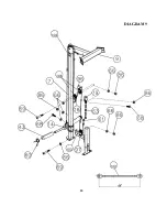


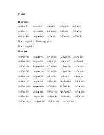

STEP 10 (See Diagram 10)
A.) Attach the 59” Lower Cable (#40) to a Pulley (#57). Attach the Pulley to the lower opening
on the Rear Vertical Beam (#6). Secure it with the Foot Plate (#16), one M10 x 3 3/8” Allen
Bolt (#73), two Ø ¾” Washers (#66), and one M10 Aircraft Nut (#86). Secure the Foot Plate
to the Cross Brace (#2) with two M10 x1” Allen Bolts (#68), four Ø ¾” Washers (#66) and
two M10 Aircraft Nuts (#86).
B.) Draw the Cable underneath the Pulley to the open bracket on the Weight Glide Base (#8).
C.) Install a Pulley to the bracket. Draw the Cable around the Pulley then upward to the Double
Floating Pulley Bracket (#18) previously installed in Step-9.
D.) Install a Small Pulley (#103) to the Bracket. Draw the Cable around the Pulley then
downward to the open bracket on the Pulley Support Frame (#97). Secure the end of the
Cable to the bracket with one M10 x 1” Allen Bolt (#68), two Ø ¾” Washers (#66) and one
M10 Aircraft Nut (#86).
E.) Connect the Shiver Bar (#30) to a Long Chain (#64) with a C-clip (#61). Connect the long
Chain to the Cable with another C-clip.
19
Summary of Contents for F-SM
Page 4: ...3 SMITH MACHINE HARDWARE PACK...
Page 5: ...4...
Page 6: ...SMITH MACHINE HARDWARE PACK 5...
Page 9: ...DIAGRAM 2 8...
Page 14: ...CABLE LOOP DIAGRAM 13...
Page 17: ......
Page 19: ...DIAGRAM 9 18...
Page 22: ...EXPLODED DIAGRAM 21...


