


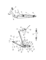
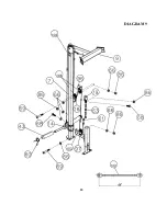


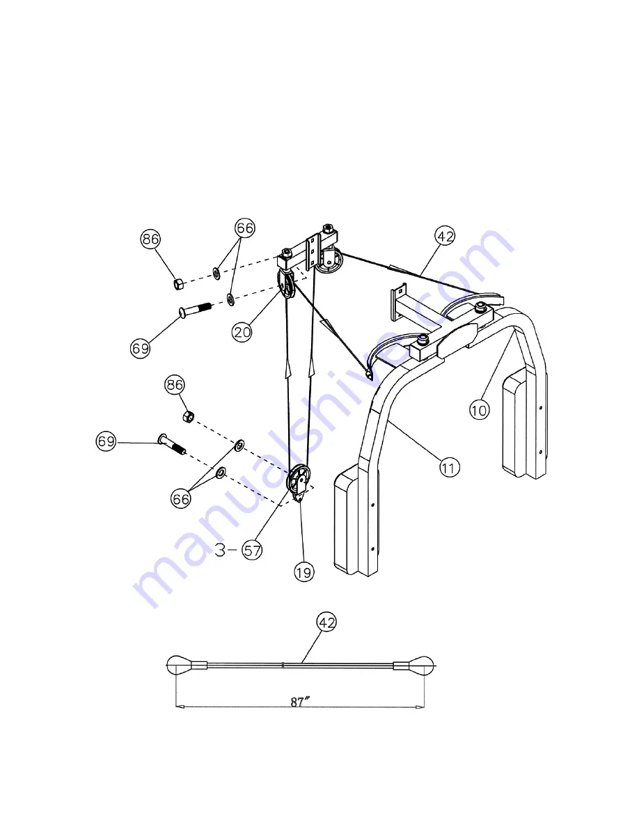
STEP 7 (See Diagram 7 & Cable Loop Diagram)
A.) Attach one end of 87” Butterfly Cable (#42) to the clip on Right Butterfly (#11). Draw the Cable to
the right Swivel Pulley Bracket (#20).
B.) Attach a Pulley (#57) to the Bracket. Secure it with one M10 x 1 ¾” Allen Bolt (#69), two Ø ¾”
Washers (#66), and one M10 Aircraft Nut (#86).
C.) Draw the Cable around the Pulley then downward. Attach a Single Floating Pulley Bracket (#19)
to the Cable. Repeat Procedure B above to install a Pulley. Let the Bracket hanging for now.
D.) Draw the Cable around the Pulley then upward to the left Swivel Pulley Bracket. Repeat
Procedure B above to install a Pulley to the Bracket.
E.) Draw the Cable around the Pulley then clip to the Left Butterfly (#10).
14
Summary of Contents for F-SM
Page 4: ...3 SMITH MACHINE HARDWARE PACK...
Page 5: ...4...
Page 6: ...SMITH MACHINE HARDWARE PACK 5...
Page 9: ...DIAGRAM 2 8...
Page 14: ...CABLE LOOP DIAGRAM 13...
Page 17: ......
Page 19: ...DIAGRAM 9 18...
Page 22: ...EXPLODED DIAGRAM 21...


