Forbest 4188 Series User Manual Download Page 7


      8   


      III. Main Technical Indicators: 

1. 


Power source input

DC 9-13.5V


2. 

  Camera module: 

1) 

  Image sensor: 1/3" color CMOS PC1099 

2) 

  Effective Pixel Array: 976 (H) x 496(V) 

3) 

  Horizontal resolution: 900TV LINES 

4) 

  Minimum illumination: 0.01LUX/F1.2 

5) 

  SNR: >45dB (AOC on) 

6) 

  Video Output: 1.0 Vp-p / 75

Ω

(CVBS) with horizontal dynamic balance 

7) 

  Input voltage: DC 9-13.5V 

8) 

  Current consumption: 65mA Max(ALL LEDS LIGHTS ON

200mA) 

3. Lighting source: 

1) 

  LED quantity: 12pcs 

2) 

  Luminous flux: 107~114 lm

180 mA


Working Current: 0~180 mA 

3) 

  Light Cup Angle: 45°     

IV. 

External Interface: 

  CAM1: Pin 1 to 4 are separately connected to VIDEO, GND, +12V, LED. 

  CAM2: Pin 1 to 6 are separately connected to 485A, 485B, +12V, GND, NC, VIDEO.
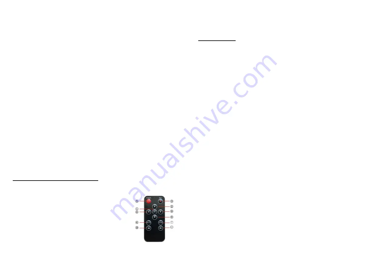
 

Remote Control 

(for 

operating DVR)   

1) 

    Enter: Enter to view and play video   

2) 

  Up: Go to up/previous item 

3) 

  REC: Start recording / snap shooting


(only available for 

new versions) 

4) 

  Setup: System setup and recording features 

5) 

  Enter: System in 

    6)      Down: Select down/next item 

    7)      Exit: Stop or exit from current menu 

    8)      Left: Select Left item 

    9)      Right: Select Right item 

    10)    Rewind: Review video 

    11)    Forward: forward video


                                                            9 

System Set-Up


1. 

IMPORTANT: When you connect the Camera to the Monitor, the power must be 

off; otherwise both units will be damaged. 

2. 

Connect  the  reel  cable  to  the  Monitor.  Connect  the  Battery  Case’s  DC  cable  to  the 

Monitor (for Simple Function Case). 

3. 

If  the  4188XX  system’s  battery  capacity  is  too  low  to  work,  please  plug  the  Power 

Adapter cord into the wall AC socket and the other end into the “DC 13.5V” jack.   

4. 

Turn on the power by pressing the POWER button on the control box for Multi-function 

Case. Turn on the power by switching on the Battery Case’s power for Simple Function 

Case. 

5. 

Press the POWER button on the front of the Monitor to turn on the 4188XX system. 

6. 

Gently lower the Camera into a pipe duct, etc and reel out the Cable until it is at the 

desired depth. 

7. 

Record the pictures if you need (see DVR Operating).   

8. 

Video Out: By using a video cable you can transfer the picture to other larger Screen. 

9. 

When you finish the job, carefully remove the Camera head from the pipe duct, etc, clean 

it with a clean, soft and dry cloth and then put the Camera into the previous position                                                                                                                                                                                                                                                                       


Summary of Contents for 4188 Series

Page 1: ...PIPE WALL VIDEO INSPECTION SYSTEMS USER MANUAL For 4188XX SERIES ASSEMBLING AND OPERATING INSTRUCTIONS Read instructions carefully before operating this system...

Page 2: ...sharply or pushed too hard otherwise it will be broken 8 We reserve the right to make any change about our products without any notice in advance DISCLAIMER OF LIABILITY WE SHALL NOT BE LIABLE TO DIS...

Page 3: ...ription Power adapter 110VAC 240VAC 13 5V DC 1700mA Battery In the case LI ION battery DC 12V 6600mAh Length of Cable 60M Camera Light Source 12PCS LED Camera Angle of View FOV 90 120 F2 8 2 42mm Came...

Page 4: ...recharge the battery Charging indicator status with the battery charging the green light will be lighted up one by one when the green light turns into the bright green the battery is fully recharged U...

Page 5: ...e device please insert it in the right port MIC on off MICROPHONE button When you need recording the voice in the process of video taping press the button and the indicator lights up Voice will be rec...

Page 6: ...HT 50 CONTRAST 50 2 COLOR 50 3 SHARP 50 4 LED BRIGHT 80 5 HUE 50 6 ENGLISH 7 After exit MENU mode the below keys have different functions 8 DOWN Press DOWN key the image change UP and DOWN Mirror func...

Page 7: ...lect Left item 9 Right Select Right item 10 Rewind Review video 11 Forward forward video 9 System Set Up 1 IMPORTANT When you connect the Camera to the Monitor the power must be off otherwise both uni...

Page 8: ...olation sheet from the Remote Control Battery 3 Press the Remote Control Button 5 to enter the Recording system you can see DVR system Recorder PLAY VIDEO manual on the screen 4 Insert your USB stick...

Page 9: ...ile Whenyouenter playvideo mode thesetwill display all oftheavailablevideofiles onthescreen Youcan use or buttontoselectdesiredvideoandpress ENT buttontoplay Press and hold or button to go to previous...

Page 10: ...Backspace Delete To delete Enter Enter Key Shift Key Input the symbol on the corresponding key space key Space bar Fn PgUp Page up Fn PgDn Page down 15 Video Player Software Installation Generally th...

Page 11: ...2 Check the camera and screw off 3 Clean the camera pins 4 Check the pins and find if they are in the same level The camera has weak or no light Press the MENU button locate the LED brightness setting...

Reviews: