background image

11 

2-3. How to Replace a Card 

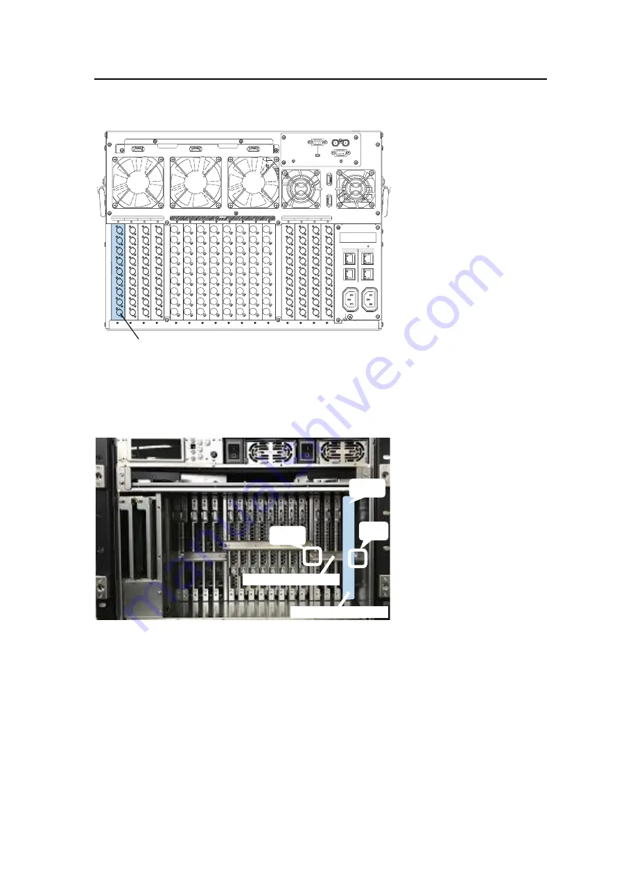
The following procedure shows how to replace the card in INPUT1 to a new input card. 
 
(1)  Detach all the BNC cables connected to the INPUT1 connector ports. 


(2)  Unfasten four fixing screws on the front panel and detach the front panel. 
(3)  Shutdown the INPUT1 slot using [SETTING > SLOT SHUTDOWN] menu in Menu Display. 

See Sec. 4-2-2. “Turning ON/OFF an Input/ Output Card” in the MFR-4100 Operation Manual 
for details. 

(4)   Remove the two screws on both sides of the card stopper and detach the stopper. 
(5)  Grab the INPUT1 slot card handle and slowly remove (pull out) the card. 


(6)  Insert a new card into the INPUT1 slot and push it in until the hole becomes entirely visible. 

Confirm the slot number and direction before card insertion. (See Step (4). in Sec. 2-2. 
“How to Install a New Card.”) 

(7)  Re-install the card stopper removed in Step (4). 
(8)  Turn the INPUT1 slot ON using [SETTING > SLOT SHUTDOWN] menu in Menu display.  

See Sec. 4-2-2. “Turning ON/OFF an Input/ Output Card” in the MFR-4100 Operation Manual 
for details. 

(9)  Check whether INPUT1 slot status is normal using [STATUS > SLOT] menu in Menu display. 

(After installing the card, it takes about 10 seconds for the status to be applied in the menu.) 
(See Sec. 4-1-4. “STATUS > SLOT” in the MFR-4100 Operation Manual for details.) 

(10) Re-install the front panel. 
 
The card replacement is now complete. 

(4) 

Card stopper 

(5) 

(4) 

INPUT1 slot 

INPUT1 slot 

FAN 1

FAN 2

FAN 3

23 2C

SERIAL

422

ALARM

REF IN

FAN 4

FAN 5

CPU1

CPU2

M

F

R

-L

A

N

P

C

-L

A

N

P

C

-L

A

N

M

F

R

-L

A

N

A

C

1

0

0

-2

4

0

V

 5

0

/6

0

H

z

 IN

A

C

1

0

0

-2

4

0

V

 5

0

/6

0

H

z

 IN

2

1

INPUT

5

6

7

8

1

9

2

3

4

5

6

7

8

1

9

8

7

6

5

4

3

2

9

8

7

6

5

4

3

2

1

1

2

3

4

5

6

7

8

9

8

7

6

5

4

3

2

1

1

2

3

4

5

6

7

8

9

9

8

7

6

5

4

3

2

1

1

2

3

4

5

6

7

8

9

9

8

7

6

5

4

3

2

1

9

9

9

9

8

8

8

8

7

7

7

7

6

6

6

6

5

5

5

5

4

4

4

4

3

3

3

3

2

2

2

2

1

1

1

1

OUTPUT

INPUT

1

2

3

4

9

9

9

9

8

8

8

8

7

7

7

7

6

6

6

6

5

5

5

5

4

4

4

4

3

3

3

3

2

2

2

2

1

1

1

1

Summary of Contents for MFR-9SDI

Page 1: ...MFR 9SDI12GA MFR 9SDO12GA MFR 9SDI MFR 9SDO 3rd Edition INSTALLATION GUIDE...

Page 2: ...r received items against the packing lists below Check to ensure no damage has occurred during shipment If damage has occurred or items are missing inform your supplier immediately Packing List ITEM Q...

Page 3: ...R 9SDI12GA MFR 9SDI is an input card for MFR 4100 MFR 6100 units MFR 9SDO12GA MFR 9SDO is an output card for MFR 4100 MFR 6100 units Open the front panel and see the product label as shown below to id...

Page 4: ...5 12 OUTPUT1 8 MFR 9SDO12GA or MFR 9SDO Up to 8 cards IMPORTANT Do not install MFR 9SDI12GA cards into slots located just left of an MFR 9SDI card viewed from the rear If an MFR 9SDI12GA is installed...

Page 5: ...4 4 5 5 5 5 5 5 5 5 6 6 6 6 6 6 6 6 7 7 7 7 7 7 7 7 8 8 8 8 8 8 8 8 9 9 9 9 9 9 9 9 INPUT 5 6 7 8 SLOT INPUT OUTPUT INPUT 1 2 3 4 1 2 3 4 5 6 7 8 5 6 7 8 1 1 1 1 2 2 2 2 3 3 3 3 4 4 4 4 5 5 5 5 6 6 6...

Page 6: ...72 x 45 72 x 36 72 x 27 72 x 18 72 x 9 7 63 x 72 63 x 63 63 x 54 63 x 45 63 x 36 63 x 27 63 x 18 63 x 9 6 54 x 72 54 x 63 54 x 54 54 x 45 54 x 36 54 x 27 54 x 18 54 x 9 5 45 x 72 45 x 63 45 x 54 45 x...

Page 7: ...99 x 18 99 x 9 10 90 x 144 90 x 135 90 x 126 90 x 117 90 x 108 90 x 99 90 x 90 90 x 81 90 x 72 90 x 63 90 x 54 90 x 45 90 x 36 90 x 27 90 x 18 90 x 9 9 81 x 144 81 x 135 81 x 126 81 x 117 81 x 108 81...

Page 8: ...ng slots BNC cables cannot be connected or BNC connectors or BNC cables may be damaged Check the card installation status Follow the procedure below 1 Unfasten four fixing screws on the front panel an...

Page 9: ...nsert a new card into the OUTPUT1 slot and push it in until the hole becomes entirely visible Confirm the slot number and direction before card insertion 5 Re install the card stopper removed in Step...

Page 10: ...onds for the status to be applied in the menu See Sec 4 1 4 STATUS SLOT in the MFR 4100 Operation Manual for details 8 Re install the front panel A new card installation is now complete To use inputs...

Page 11: ...Step 4 8 Turn the INPUT1 slot ON using SETTING SLOT SHUTDOWN menu in Menu display See Sec 4 2 2 Turning ON OFF an Input Output Card in the MFR 4100 Operation Manual for details 9 Check whether INPUT1...

Page 12: ...ont panel and detach the front panel 2 Open the STATUS SLOT menu in the Menu display See Sec 4 1 4 STATUS SLOT in the MFR 6100 Operation Manual for details The illustration below shows the right place...

Page 13: ...stopper 3 Detach the OUTPUT1 slot blank panel 4 Insert a new card into the OUTPUT1 slot and push it in until the hole becomes entirely visible Confirm the slot number See the figure on page 5 and dire...

Page 14: ...using STATUS SLOT menu in Menu display After installing the card it takes about 10 seconds for the status to be applied in the menu See Sec 4 1 4 STATUS SLOT in the MFR 6100 Operation Manual for detai...

Page 15: ...l using STATUS SLOT menu in Menu display After installing the card it takes about 10 seconds for the status to be applied in the menu See Sec 4 1 4 STATUS SLOT in the MFR 6100 Operation Manual for det...

Page 16: ...Tel 39 039 916 4811 Fax 39 039 878 140 FOR A UK Limited Trident Court 1 Oakcroft Road Chessington KT9 1BD U K Tel 44 0 20 3044 2935 Fax 44 0 20 3044 2936 FOR A Italia S r l Via Volturno 37 20861 Brug...

Reviews: