


- 58
-
INST
ALLA
TION
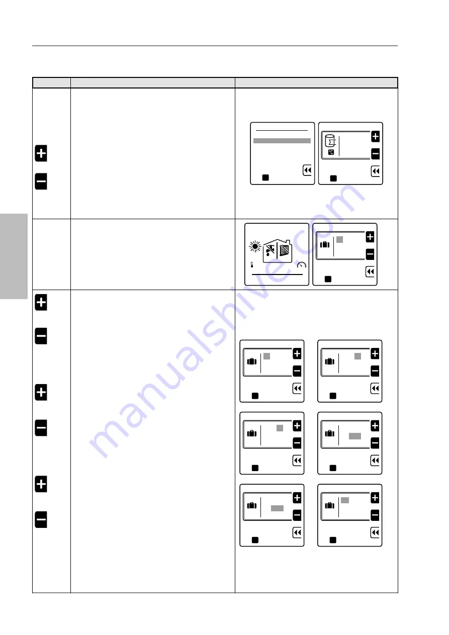
Key to press
Description
Display
D
C
A
OR
A
C
to select "2. DHW temperature"
to confirm and access the selected line
to set the desired value (for water heaters with probe
only) (*)
to confirm set value and go back to line "2. DHW
temperature"
to confirm
1. CH holiday setpoint
2. DHW holiday setpoint
to confirm
oK
Boiler t. setpoint
30
to confirm
oK
E
G
to return to start screen
to view the "Holiday start" date
data
Ext.temp.
7
o
C
69
o
0.0
OFF OFF
ora
Holiday start
20 / 10
2012
to confirm
oK
a
a
A
A
OR
A
D
A
OR
A
D
A
OR
A
C
to set holiday start day
to select the month
to set the month
to select the year
to set the year
to confirm set values and enter the "Holiday end"
screen.
NOTE: for holiday end day, month and year settings,
follow the "Holiday start" procedure.
Holiday start
30 / 10
2012
to confirm
oK
a
a
A
Holiday start
30 / 10
2012
to confirm
oK
a
a
A
Holiday start
30 / 12
2012
to confirm
oK
a
a
A
Holiday start
30 / 12
2012
to confirm
oK
a
a
A
Holiday start
30 / 12
2012
to confirm
oK
a
a
A
Holiday end
01 / 12
2012
to confirm
oK
a
a
A
maui KR 115