background image

About motor brushes

Two graphite brushes convey electric power to the motor commuta-

tor. Brushes are a consumable item, and have a lifetime of about 650
operating hours. Operating without the air intake filter lets airborne dirt
and moisture enter the motor; this can reduce brush life substantially.
When brushes are worn the motor does not operate properly. 

If you must replace motor brushes, we recommend installing a

M

OTOR

S

AVER

brush on one side. The M

OTOR

S

AVER

brush contains an

insulating pin to shut down the motor when the brush is worn,
minimizing the chance that the motor will drag and scratch the
commutator. Replacement brush part numbers are:

030: Brush kit (two standard brushes), 120 VAC. 
032: Brush kit (two standard brushes), 240 VAC
033: Brush kit (one standard, one M

OTOR

S

AVER

), 120 VAC. 

034: Brush kit (one standard, one M

OTOR

S

AVER

), 240 VAC

How to replace motor brushes

Unplug power cord to prevent shock. Remove front housing (see

“Simple Workstation”) to access the motor. Identify the two motor brush
housings on opposite sides at the top of the motor.

Insert a small flat blade screwdriver between the motor wire/termi-

nal and the plastic brush housing. Gently pry terminal out, pushing it
towards the commutator until it is loosened. Take care not to break the
terminal contact or the wire. If the plastic brush housing is very tight, heat
slightly with a hair drier or heat gun to soften before sliding the wire/ter-
minal out. Repeat for the second brush.

Remove two Phillips head screws and retaining bracket holding one

motor brush. Lift brush off motor frame and discard.

Hold replacement brush in position (tab pointed down). Press the

motor wire terminal (flat brass piece) partially into the brush assembly,
between the brass shell and the plastic housing.

Slide the brush assembly towards the commutator until the tab seats

in the notch on the motor frame. Replace retaining bracket and two
screws. Then slide or pry the wire terminator securely back into the brush
housing with the screwdriver.

Repeat for other brush.

11

Summary of Contents for 6208xx

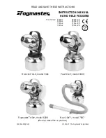
Page 1: ...208 Pow R Jet model 6309 Micro Jet ULV model 7401 Noz L Jet model 7807 For Models 6208xx 6208xxCE 6309xx 6309xxCE 7401xx 7401xxCE 7807xx 7807xxCE showing intake filter in position READ AND SAVE THESE...

Page 2: ...tems and socket configurations Electromagnetic Emissions Models with CE in position zz 7 8 of the part number 6208xyCE 6309xyCE 7401xyCE and 7807xyCE are shielded against the generation of ratio inter...

Page 3: ...Do not unplug by pulling on cord To unplug grasp the plug not the cord 5 Unplug from outlet when not in use and before servicing or cleaning 5 Do not operate any appliance with a damaged cord or plug...

Page 4: ...placement of the cord or plug is necessary do not connect the equipment grounding conductor to a live terminal Check with a qualified electrician or serviceman if the grounding instructions are not co...

Page 5: ...information obtain directions for use and safety precautions including personal protective equipment respirator face mask special clothing from the chemical manufacturer or distributor Keep an intake...

Page 6: ...The liquid flow rate determines the size of the fog droplets formed by the machine Several factors influence the liquid flow rate the density and viscosity of the liquid the setting of the flow contr...

Page 7: ...gressively larger droplets wet fog fine mist Liquid flow is regulated by a control valve or for certain models a fixed flow restrictor in the liquid intake line Calibration Adjust the angle of the noz...

Page 8: ...ive plastic tank liner and position it inside tank new units ship with a tank liner in place The top of the liner should extend over and outside the top lip of the tank Add fogging liquid to the tank...

Page 9: ...oth arc Sudden movements can impose excessive torque on the rapidly spinning fan blades and could cause premature blade failure Cleaning the Fogger A Normal cleanup When fogging is complete remove the...

Page 10: ...80 for a package of 10 Cleaning the nozzle Deposits which form on the nozzle can degrade performance Try to dissolve deposits with an appropriate mild solvent soapy water vinegar solution kerosene etc...

Page 11: ...move front housing see Simple Workstation to access the motor Identify the two motor brush housings on opposite sides at the top of the motor Insert a small flat blade screwdriver between the motor wi...

Page 12: ...in proper sequence Take care that the bent tab on the torque ring faces the motor and is seated in the small hole on the motor frame Reconnect electrical lines as shown on the circuit diagram Replace...

Page 13: ...pen this style press release tab and pull fitting apart The other style uses a locking collet with spring clips inside the receptacle to secure the connector To open this style connector release the l...

Page 14: ...0 60 Hz 240V MODELS STANDARD UNIT CORD PLUG WITH EARTH to 220 240VAC 50 60 Hz GROUND RIVET BLUE BROWN M BLACK WHITE 120V MODELS STANDARD UNIT GREEN M GREEN BLUE GREEN POWER HEAD HOUSING EMI FILTER CE...

Page 15: ...Rate 7401 0 10 oz 300 ml min adjustable 7807 0 10 oz 300 ml min adjustable plus liquid ON OFF toggle valve on wand 6208 0 10 oz 300 ml min adjustable 6309 10 oz 300 ml min not adjustable a Droplet Siz...

Page 16: ...and oil resistant vinyl Fittings brass stainless steel optional Nozzle Celcon acetyl copolymer Dimensions LxHxDia 12 5 x 15 4 x 8 6 in 32 x 39 x 22 cm Hose Wand 7807 36 in 91 cm hose and either 38 in...

Page 17: ...ified voltage This warranty is limited to the original purchaser only and does not include claims for incidental or consequential damages resulting from the non function or malfunction of this product...

Page 18: ...n Celcon and Viton are registered trademarks of their respective owners In the interest of improving internal design operational function and or reliability The Fogmaster Corporation reserves the righ...

Reviews: