19
Dragging a second unit into the
ROUTED
area in the same way, and placing it below the first unit,
will assign the second block of routings; again, the number of additional channels routed will be
determined by RedNet type.
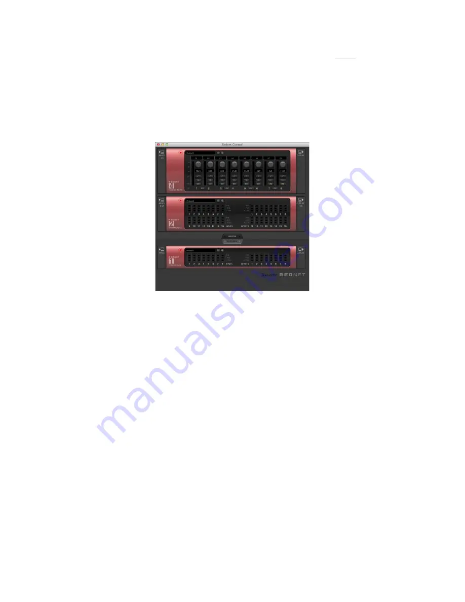
In the example shown below, the first unit to be assigned (the top panel) is a RedNet 4 and the second
a RedNet 2. Thus the host computer will have its Audio Inputs 1 – 8 mapped to the physical inputs
of RedNet 4 and Audio Inputs 9 – 24 mapped to the physical inputs of RedNet 2. Audio Outputs 1 -16
will only be available from RedNet 2, because RedNet 4 is an input-only device.
RedNet units may be unassigned in the same manner, by dragging them from the
ROUTED
area to
the
AVAILABLE
area. Note that right-clicking anywhere in the RedNet Control window (except the
metering areas) will open the utility menu, which contains the option
UNROUTE ALL
. Selecting this
will unassign all units in the system. See “Utility menu” on page 21.
If you hover the cursor over the channel number of any unit in the
ROUTED
area, you will see tooltip
text confirming which input or output channel of the RedNet PCIe card the unit channel is mapped
to. In the example given above, if you hover over Input 2 of the RedNet 2’s virtual panel, you will see
a tooltip indicating:
-> PCIe Channel 10
In the case of outputs, the tooltip arrow position is reversed, thus:
PCIe Channel 2 ->
Other routing possibilities are available from Dante Controller; see “Using Dante Controller” on
page 22 for more information.


