Focal Point SUPA 400 Installation, Servicing And User Instructions Manual Download Page 14

OPERATING THE FIRE

The pilot is visible through the underside of the left hand front coal strip.
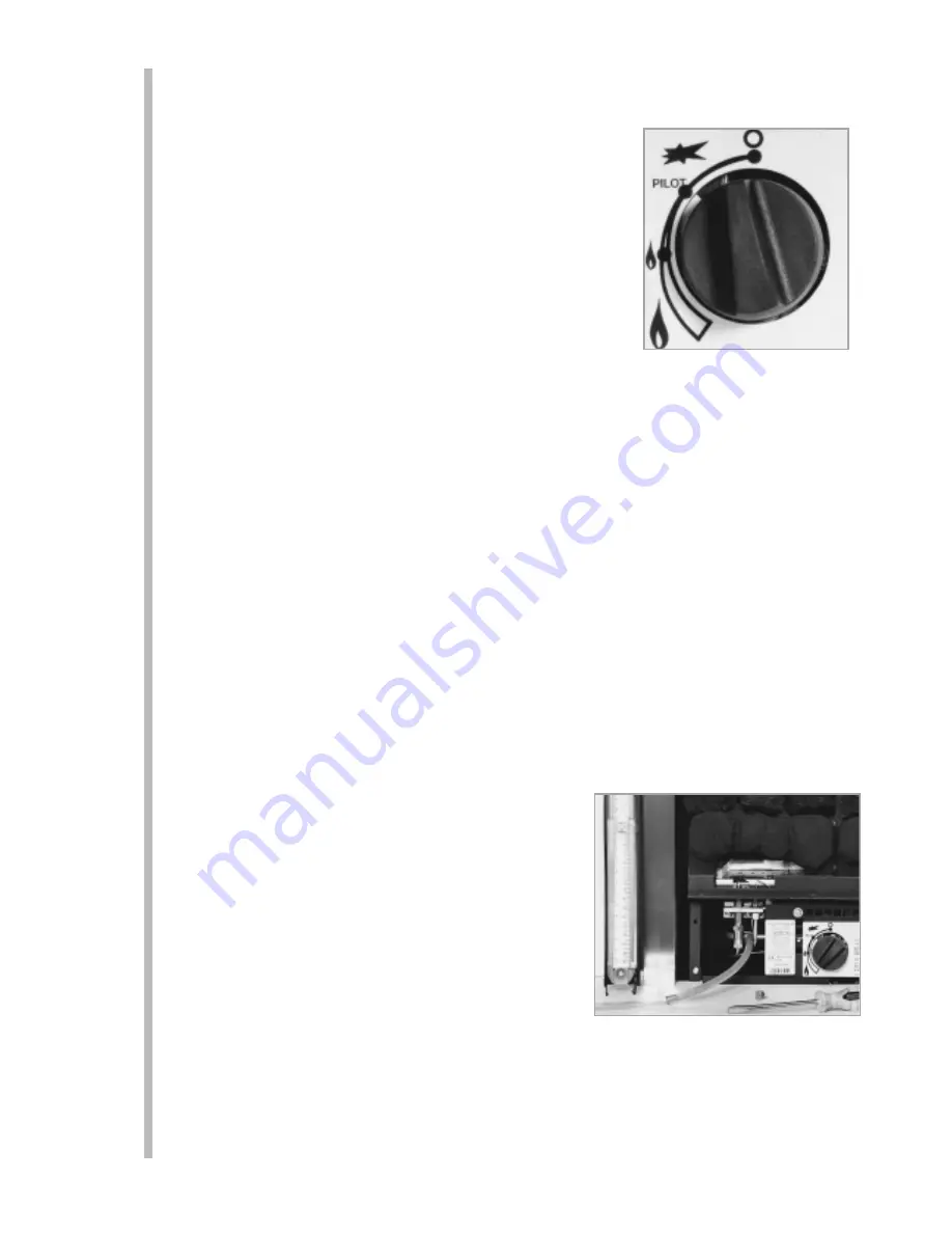
Push in and turn the control knob to the SPARK position, and hold there for
a few seconds.

Continue turning anti-clockwise through the spark click to the PILOT light
position, ensuring the pilot has lit. If not, return the knob clockwise, and
repeat.

When the pilot lights after the spark, keep the knob depressed for
approximately ten seconds. Now release the knob and the pilot should stay
alight. If not, retry ignition. If the pilot is extinguished during use, wait three
minutes before repeating the ignition procedure.

To achieve the HIGH setting, push the control knob in slightly and continue turning anti-clockwise to the high
position. The main burner should light after a few seconds.

To decrease the setting to LOW, turn the control knob clockwise to the low setting.

To turn to the PILOT position from the HIGH or LOW positions, press the control knob in, and return to the pilot
position and release.

To turn the fire OFF, keep the knob pressed in, return to the off position and release.

SPARK FAILURE

The gap between the spark electrode and the pilot should be 3.5 - 4.5mm to produce a good spark. There should
be no need to adjust this. If under any circumstances the electric spark fails, the pilot may be lit manually by
proceeding with the ignition sequence as previously described, and after turning the control knob through the
spark position, the knob should be held in and the pilot lit with a taper.

FLAME CONTROL LEVER

On Natural Gas appliances there is a flame control lever behind the ashpan door that varies the flame colour from
blue to a decorative yellow. The customer should be instructed in it’s position and that it can be used to vary the
flame picture as required. To minimise any carbon deposition that may occur, it is recommended that the fire is
used on the COKE setting for the first and last periods (approximately 20 mins.) of each use.

SETTING PRESSURE

Remove the screw from the pressure test point, situated on the
main injector pipe by the pilot, and attach a U gauge. Light the fire
on the HIGH setting.

The setting pressure should be in accordance with the figures
stated on page 2 of these instructions. The fire is factory set to
achieve these pressures, and any significant variation could
indicate a supply problem.

If the pressure is too high, the gas supply meter may be set
incorrectly. This should be checked with the fire running and if
necessary reset by the gas supplier.

If the pressure is too low, then check the meter governor pressure with the appliance running. If this is incorrect
it will need to be reset by the gas supplier. If the setting pressure is too low, but the meter pressure is acceptable,
then a problem in the supply pipework is to be suspected. This will be dirt and debris, kinked or inadequate size
pipes, restriction in a fitting or solder flashing across a joint. (NOTE: you will not get an accurate reading of the
inlet pressure with a pressure gauge on the end of the supply pipe - this is the static pressure in the system. You
must use a T piece and measure the supply pressure with the fire on High - the dynamic pressure).

11

14.1

14.2

14.3

14.4

Summary of Contents for SUPA 400

Page 1: ......

Page 2: ......

Page 3: ...a competent person in accordance with Gas Safety Installation and Use Regulations 1998 It is strongly recommended that a CORGI registered engineer be used for this purpose Read all these instructions...

Page 4: ...se regulations could lead to prosecution and deem the warranty invalid This appliance must be installed in accordance with the rules in force and used only in a sufficiently ventilated space Consult a...

Page 5: ...ing a smoke pellet or similar to ensure proper draw and that leakage is not evident at any joints Repair and re test as necessary before the appliance is installed The flue must be connected to only o...

Page 6: ...ught device must be sealed off The opening wall must be non combustible and have adequate flat surface for appliance sealing The appliance requires a hearth with non combustible surface of at least 12...

Page 7: ...ID FUEL OR OIL BURNING APPLIANCES X Dimension 60mm VENTILATION No purpose provided ventilation is normally required for this appliance The requirements of other appliances operating in the same room o...

Page 8: ...hearth may be drilled to allow plugs and screws to secure installation It is important that the sealing requirements of the appliance are met at all times and that the flue box is well sealed to any b...

Page 9: ...g the two screws through the tray legs Remove the transit screw securing the rear ledge of the firetray to the firebox This will no longer be required The tray is now free and may be lifted away Knock...

Page 10: ...ion SCREW FIXING For fixing by screw mark and drill the fireframe or base and the relevant points in the opening or on the wall Rawlplugs will again be required Pre punched holes are not provided for...

Page 11: ...e loose tensioning cables through the holes into the firebox You may need to temporarily adjust the outlet deflector at this point as described in the Fitting the firebox section Thread the tensioner...

Page 12: ...ng the coal shapes are facing forwards The legs on the coals have a serrated front face which is intended to give a tight interference fit in to the tray and at the same time remove a small portion of...

Page 13: ...ifferent type Never throw rubbish or other matter onto the coal bed FITTING THE DECORATIVE FRAME AND FRONT The appliance is supplied with a decorative frame in a variety of finishes The frame is held...

Page 14: ...taper FLAME CONTROL LEVER On Natural Gas appliances there is a flame control lever behind the ashpan door that varies the flame colour from blue to a decorative yellow The customer should be instructe...

Page 15: ...ce manufacturer If the fire is not spilling then further guidance should be sought using the Troubleshooting section as a guide TESTING FOR SPILLAGE Close all doors and windows to the room containing...

Page 16: ...trol plate 5 Disconnect the gas supply and remove the two securing screws in the tray legs 6 Remove the burner tray 7 Remove the firebox as detailed in the relevant section 8 Check the area behind the...

Page 17: ...remove the largest of the three screws on the face of the valve Slide the filter out and clean away any debris that may have accumulated The filter element should also be blown clean This component sh...

Page 18: ...lderly or infirm are concerned Combustible items such as flooring and furniture and soft wall coverings such as blown vinyl or embossed paper may discolour if fitted too close to the fire See relevant...

Page 19: ...is will have been carried out by your CORGI registered installer For Republic of Ireland ventilation may be required see IS 813 ICP3 IS 327 and any other rules in force OPERATING INSTRUCTIONS The pilo...

Page 20: ...the firebed should be periodically removed by a competent person Large deposits could indicate deterioration of the flue This should be repaired by a competent person and the fire serviced before furt...

Reviews: