background image

www.fmiproducts.com

122272-01D

9

installation

Continued

FLASHING INSTALLATION (V6F-10DM 

OR V12F-10DM)

Determine flashing to be used with roof open-

ing chart. Slide flashing over pipe until base is 

flat against roof. Replace as many shingles as 

needed to cover exposed area and flashing 

base. Secure in position by nailing through 

shingles  (see  Figure  13).  DO  NOT  NAIL 

THROUGH FLASHING CONE.

Nail Only 

Outer 

Perimeter 

of Flashing

Storm 

Collar

Flashing

Cone

Underlap 

Shingles 

at Bottom

Overlap 

Shingles Top 

and Sides Only

Figure 13 - Flashing Installation

Installing Flashing on a Metal Roof

When installing the flashing on a metal roof, 

it is required that putty tape be used between 

the flashing and the roof. The flashing must be 

secured to the roof using #8 x 3/4" screws and 

then sealed with roof coating to prevent leak-

age through the screw holes. A roof coating 

must also be applied around the perimeter of 

the flashing to provide a proper seal.

Storm Collar Installation (SC2-1)

Place storm collar over pipe and slide down 

until it is snug against open edge of flashing 

(see Figure 14). Apply waterproof caulk around 

perimeter of collar to provide a proper seal.

Figure 14 - Storm Collar

Chimney 

Pipe

Waterproof 

Caulk

Storm 

Collar

Flashing

Terminations/Spark Arrestor

Fireplace  system  must  be  terminated  with 

listed round top or chase terminations. In any 

case, refer to installation instructions supplied 

with termination.

 CAUTION: Do not seal open-

ings  on  the  rooftop  flashing. 

Follow installation instructions 

provided with termination being 

used.

Secure 

Termination 

to Outer 

Pipe with 3 

Screws

RLT-12D 

(Shown)

Level of 

Flue Gas 

Outlet

Stainless 

Inner Flue 

Pipe

Waterproof 

Caulking

Storm 

Collar

Flashing

Underlap 

Shingles

Figure 15 - Termination

Overlap 

Shingles (Top 

and Sides of 

Flashing Base)

CHASE INSTALLATIONS

Instructions for chase installations are includ-

ed with the chase style termination chosen. 

In  a  multiple  chase  installation,  be  sure  to 

provide  adequate  distance  between  termi-

nations to prevent smoke spillage from one 

termination to another. Terminations must be 

separated a minimum of 24" center to center 

and stacked at a minimum vertical height dif-

ference of 18" (see Figure 16, page 10).

Note: If a decorative shroud is to be installed, 

contact the manufacturer for specifications.

Summary of Contents for WCM-48F

Page 1: ...ndards or for use with a vent free gas log heater approved to ANS Z21 11 2 standard ThiswoodburningfireplacecomplieswithUL127 CAN ULC S610 M87 standard as a FACTORY BUILT APPLIANCE FOR CANADA The authority having jurisdiction such as the municipal building department fire department etc should be contacted before installation to deter mine the need to obtain a permit INSTALLER Leave this manual wi...

Page 2: ...PRODUCTS LLC in combination with a FMI PROD UCTS LLC fireplace system Proper installation is the most important step in ensuring safe and continuous operation of the fireplace Consult the local building codes as to the particular requirements concerned with the installation of all factory built fireplaces WARNING Do not install a fireplaceinsertinthisboxunless the manufacturer s instructions with ...

Page 3: ...r Using Straps Provided Hearth Spacer Required for Combustible Floor 0 to Bottom 12 Min Each Side Hearth Extension 72 X 20 Outside Air Access Location 1 5 Airspace Back and Sides 2 Chimney Airspace Clearance to Combustible Material No Combustible Material on Front Face Except for Mantel Applications Gas Line Access Location 18 Min to Perpendicular Wall Safety Continued WARNING Alwaysleaveglass doo...

Page 4: ...y at the level of the flue gas outlet see Figure 15 page 9 Framing 1 Frame the opening for the fireplace using the dimensions shown in Figures 1 and 2 2 If the fireplace is to be installed directly on carpeting tile other than ceramic or any combustible material including wood flooring the fireplace must be installed 60 875 65 7 71 5 76 375 31 625 Secure Fireplace To Hearth Spacer Using Straps Pro...

Page 5: ...Seal Gap Fireplace Front Ember Protector Fireplace Front Raised Hearth Fireplace Front Elevated Ember Protector Ember Protector Seal Gap Hearth Extension Mantels A mantel may be installed if desired see Figure 4 Woodwork such as wood trims mantels or any other combustible material projecting from the front face must not be placed within 12 of the fireplace opening Combustible materials above 12 an...

Page 6: ...pipe sections are locked together When installing double wall snap lock chimney to gether it is important to assure joint between chimney sections is locked Check by pulling chimney upward after locking Chimney will not come apart if properly locked It is not necessary to add screws to keep chimney together exception see Figure 9 page 8 Figure 5 Outside Air Kit Secure to Collars with Metal Tape Sc...

Page 7: ...18 24 36 48 4 3 8 16 3 8 ELBOW SET ONLY 9 3 4 25 1 2 1 12 3 4 30 3 4 1 15 34 3 4 1 18 40 1 1 21 1 4 46 1 4 1 23 3 4 49 1 4 1 1 27 3 4 56 3 4 1 30 60 3 4 1 1 33 66 1 36 71 1 1 38 1 4 75 2 41 1 4 80 1 4 1 1 1 45 86 3 4 2 46 3 4 89 1 2 1 1 1 51 97 1 1 53 1 4 101 2 56 1 4 106 1 4 2 59 1 4 111 1 2 1 1 1 61 3 4 115 1 2 1 2 64 3 4 120 3 4 1 2 68 1 4 127 2 1 70 130 1 1 2 74 1 4 137 1 2 1 2 1 76 3 4 141 1 ...

Page 8: ... Screws or Staples Min of 8 Firestop Spacer Screws or Staples Min of 8 Penetrating roof To maintain a 2 clearance to pipe on roof with a pitch a rectangular opening must be cut 1 Determine center point through which pipe will penetrate roof 2 Determine center point of roof Pitch is the distance the roof drops over a given span usually 12 3 Use roof opening chart Figure 12 to determine correct open...

Page 9: ...ainst open edge of flashing see Figure 14 Apply waterproof caulk around perimeter of collar to provide a proper seal Figure 14 Storm Collar Chimney Pipe Waterproof Caulk Storm Collar Flashing Terminations Spark Arrestor Fireplace system must be terminated with listed round top or chase terminations In any case refer to installation instructions supplied with termination CAUTION Do not seal open in...

Page 10: ...10 Foot Rule Seal Opening with Refractory Cement Outside of Fireplace Gas Line Conduit Repack Insulation Incoming 1 2 Black Iron Pipe Side Firebrick Finished Side Provide Enough Threaded End for Fitting Connection Figure 18 Gas Line Installation Optional Gas Line Installation Gas line hook up should be done by your sup plier or a qualified service person Note Before you proceed make sure your gas ...

Page 11: ...ing Brick Brick Stamped Number Location Brick Housing Flanges Brick Installation IMPORTANT Installationofbrick should be done after the fire place is placed in a permanent location Each brick housing is stamped with a number full size bricks are not stamped These num bers will help identify the brick when installing It is important to install these bricks exactly as instructed Press brick firmly i...

Page 12: ... 0 0 2 S 0 0 2 S 0 0 8 S 0 1 9 S 0 1 9 S 0 1 9 S 0 2 3 S026 S027 S028 S029 S030 F U L L F U L L F U L L F U L L S 0 3 4 F050 F049 F049 F049 F049 F049 F049 F049 F049 F049 F055 F056 F053 F055 F055 F055 S021 or S006 S012 S025 S024 F054 S042 F051 F054 F050 S041 S039 S038 S037 S001 S003 S007 S022 S040 S001 S003 F U L L F U L L F U L L F U L L F U L L F U L L F U L L S 0 0 6 F U L L F U L L F U L L F U ...

Page 13: ... S014R S014W 1 S015R S015W 1 S016R S016W 1 S019R S019W 3 S020R S020W 11 S021R S021W 1 S023R S023W 1 S024R S024W 1 S025R S025W 1 S026R S026W 1 S027R S027W 1 S028R S028W 1 S029R S029W 1 S030R S030W 1 REAR UPPER REFRACTORY RED IVORY QTY FULL 112140 02 FULL 112140 06 24 F054R F054W 3 S002R S002W 1 S005R S005W 2 S006R S006W 2 S007R S007W 3 S008R S008W 1 S011R S011W 1 S013R S013W 1 S014R S014W 8 S015R S...

Page 14: ...e into piping bag making sure the smaller opening is downward and over a moist towel to avoid spilling Place a wet towel over the bucket making sure it is directly on the surface of grout mixture This will keep the mixture moist and it will not dry out before use 5 Begin grouting by first doing a Filler Pass This is done by filling the joint about 3 4 full with grout mixture It is important to wor...

Page 15: ...ptional Ash Lip Kit Rail installation 1 Remove screws securing top face to firebox see Figure 22 2 Align holes on rail to be installed at top and replace screws Note Door rails are identical until spring clips are in place 3 Using remaining door rail as a template place along front row of bricks at bottom making sure rail front surface is flush with fireplace bottom face surface Mark hole centers ...

Page 16: ...rs must be fully opened before starting fire This will provide sufficient combustion air and maintain safe temperatures in firebox Figure 26 Bi Fold Glass Doors Doors Fully Closed Fireplace Front Fireplace Front Doors Fully Opened Installing Glass Doors After spring clips have been installed some adjustments may be needed Install the doors using the following steps 1 With bi fold doors completely ...

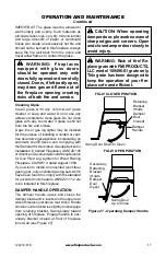
Page 17: ...laces ANSI Z21 60 orAmericanGasAssociationdraftrequirements for Gas Fired Log Lighters for Wood Burning Fireplaces Draft NO 4 dated August 1993 If you wish to install an unvented vent free gas log set only unvented gas log sets which have been found to comply with the standard for unvented room heaters ANSI Z21 11 2 are to be installed in this fireplace damper handle operation The damper handle op...

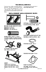
Page 18: ...y Parts Bi Fold Glass Masonry Door BDMO48E 48 Ebony BDMO48G 48 Pewter BDMO48C 48 Oiled Bronze Double Wall Pipe 12 12DM 18 12DM 24 12DM 36 12DM 48 12DM 12 12HT 18 12HT 24 12HT 36 12HT and 48 12HT 30 Offset and Return 30E 12DM and 30E 12HT Grate 109496 01 for F48 Series 123277 01 for WCM 48F Series Ember Protector 20093 Optional Outside air kit for floor installation ak4f Optional Outside Air Kit fo...

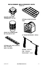
Page 19: ... Parts Continued SQUARE CHASE TOP TERMINATION STL 12D Round ToP TErminations RLT 12D and RLT 12HT Optional ASH LIP KIT Bricks AL48 Red Brick AL48I Ivory Brick Optional Hearth Spacer HS48 24 Round Woodnook DHR 24 Screen 118115 01 Rod 110146 02 Push On Nut 11418 ...

Page 20: ...122272 01 Rev D 01 10 2701 S Harbor Blvd Santa Ana CA 92704 1 866 328 4537 www fmiproducts com ...

Reviews: