FMC M12-HD Operation & Maintenance Manual Download Page 13

F M C   M 1 2 - H D   O P E R A T I O N   A N D   M A I N T E N A N C E   M A N U A L  


13


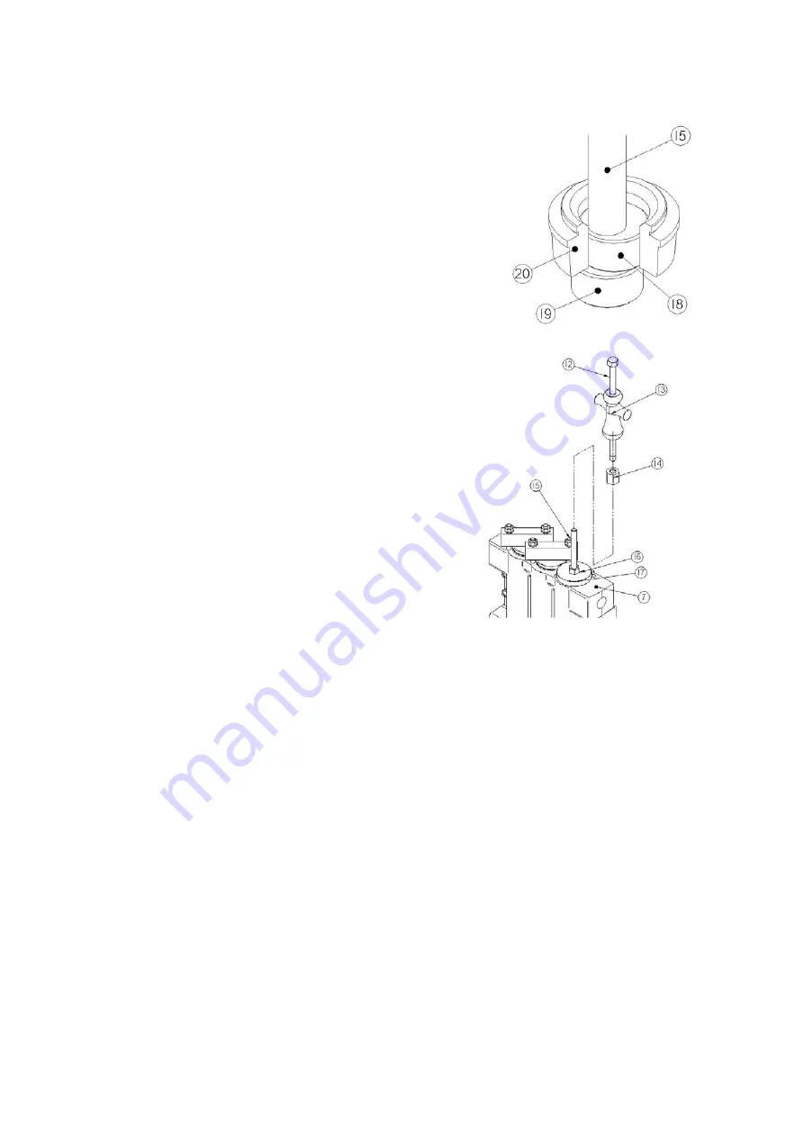
Assemble the puller guide (19) and puller eccentric (18) 
on one end of the puller stem (15) as shown.  There are 
two guides and two eccentrics provided in the kit.  Use the 
slightly larger diameter ones to remove the discharge 
valve seats.  The smaller diameter components will be 
used later when removing the suction valve seats. 


Insert the end of the puller stem down through the discharge 
valve seat (20).  Work the puller guide (19) through the center 
of the seat until it sits just underneath the seat.  Hold the 
puller stem firmly in position, then work from side to side until 
the puller eccentric (18) drops down into the ID of the seat 
and rests on the top of the guide as shown. 


Hold the puller stem (15) in this position and slide 
the strongback (17) down over the stem until it rests 
squarely on the top of the fluid cylinder (7). 


Run the puller nut (16) down the stem until it is hand 
tight on the top of the strongback.  You can now 
release the puller stem, as the components will not 
shift position with the nut in place. 


Using a heavy-duty 1-5/8” wrench, tighten the puller 
nut down against the strongback to apply force to 
the bottom of the valve seat.  Note that up to 800 ft-
lbs of torque may be required to free the valve seat 
from the fluid cylinder.  Do not exceed this value. 


In many cases, torque alone will be sufficient to free 
the valve seat.  If unsuccessful with torque alone, 
use the adapter nut (14) to connect the slide 
hammer (13) and puller bolt (12) to the puller stem 
(15).  Leave the puller nut torqued from the previous 
step.  Drive the slide hammer firmly into the head of 
the puller bolt to apply extra impact force to free the valve seat and lift out through the 
valve cover bore in the fluid cylinder. 


Repeat the previous steps to remove the suction valves that are located just below the 
discharge valves.  Replace the puller guide and eccentric with the smaller diameter parts 
provided in the kit to slide through the smaller bore of the suction valve.  It will be 
necessary to fish out the valve spring and valve from the suction valve using a variety of 
hooks and loops of string or wire since the are located too deeply in the bore of the fluid 
cylinder to be removed by hand. 


Remove the suction and discharge valves from the remaining two cylinders. 

Summary of Contents for M12-HD

Page 1: ...M12 HD Piston Pump Operation Maintenance Manual ...

Page 2: ...res specifications torque requirements and other values may be updated at any time Always contact FMC or your FMC equipment dealer for the most complete and current information before starting any repair job Contact FMC any time if you are unsure about any procedure involving FMC equipment Do not perform any operation maintenance or lubrication of this equipment until you have read and understood ...

Page 3: ...ents Short Term Storage 5 Short Term Storage in Severe Environments 5 Long Term Storage 5 Precautions During Freezing Weather 6 Lubrication Requirements 7 Suction System Information 7 Periodic Maintenance Schedule 8 Service Procedures Replacing Piston Cup Seals 9 Valve Replacement 12 Oil Seal Replacement 15 Special Tools 16 Trouble Shooting Guide 17 ...

Page 4: ...p is equipped with an external gear reducer consult the manufacturer for information about operation service and maintenance procedures required for the equipment FMC M12 pumps do not share common oil reservoirs with gear reducers Standard M12 pump designs require a liner wash system for proper operation Some systems are provided directly by FMC but most are provided by your OEM Each system is dif...

Page 5: ...ntire pump with a weather resistant covering such as a canvas or plastic tarp LongTermStorage Long term storage is defined as any period when the pump is in storage or idle for periods in excess of six 6 months Remove the piston cup seals and store them in a separate location with a controlled environment where they are protected from UV exposure If the pump has been in service flush the fluid end...

Page 6: ...the pump and cause permanent equipment damage or personal injury Whenever the pump is stored or idle in conditions that are near or below freezing any water based fluids should be removed from the pump The best way to do this is to run the pump for a few seconds with the suction and discharge lines disconnected or open to atmosphere This will clear the majority of the fluid from the pumping chambe...

Page 7: ... consult its manufacturer for oil requirements and service intervals External gear reducers do not share a common oil reservoir with the pump SuctionSystemInformation FMC pumps require a minimum Net Positive Suction Head NPSH for proper operation The calculation of NPSH available for a specific pump system is a function of pump size speed fluid temperature suction pump diameter and length and a ho...

Page 8: ...tem problems that must be addressed Daily Piston Seals Inspect Check back side of piston seals for signs of excessive leakage Replace promptly if leakage becomes excessive to avoid additional damage Daily Crankcase Oil Inspect Check for proper level and for signs of contamination Daily Liner Wash System Change Inspect Change the liner wash water and inspect the system for proper operation Insure s...

Page 9: ...mum uptime between service FMC always recommends that users replace all three pistons when service is required not just the one that shows signs of leakage Pump several gallons of clean water through the pump before service to remove the majority of mud or polymer from the fluid end components Bleed of all pressure inside pump fluid end Shut valve on inlet piping if provided to prevent flow of liq...

Page 10: ...id cylinder counterbore Push the piston assembly out through the back of the cylinder Place the flats provided on the piston extension 40 in a bench vice Remove the piston nut 44 and dissemble the remaining components Discard the piston 42 piston o ring 45 and cylinder o ring 50 Clean inspect and save the remaining components so they can be reinstalled later Take extra care to inspect the bore of ...

Page 11: ...oove Place the piston cylinder assembly into the counterbore of the fluid end and push in firmly until it is seated at the base of the counterbore Slide the cylinder clamp 48 over the cylinder and into position over the cylinder studs Install and tighten the cylinder hex nuts 46 and washers 47 Torque the nuts to 125 ft lbs in three stages to prevent cocking of the cylinder Use a wrench on the flat...

Page 12: ...clamp 4 Remove the valve cover 5 and valve cover o ring 6 from each of the three pump cylinders It may be necessary to use a pry bar in the groove provided at the base of the valve cover to loosen it from the fluid cylinder Remove the valve cover studs 4 so that the valve puller tools can sit squarely on the top of the fluid cylinder The tops of the discharge valve cages should now be visible thro...

Page 13: ...n with the nut in place Using a heavy duty 1 5 8 wrench tighten the puller nut down against the strongback to apply force to the bottom of the valve seat Note that up to 800 ft lbs of torque may be required to free the valve seat from the fluid cylinder Do not exceed this value In many cases torque alone will be sufficient to free the valve seat If unsuccessful with torque alone use the adapter nu...

Page 14: ... 11 in the puller kit to torque the cage Lower the suction valve assembly into position on the port taper of the fluid cylinder lift slightly then allow to drop straight into the port If the seat drops straight it will seize in the taper and cannot be removed by hand Drive the valve assembly into the port taper using several sharp blows from a mallet The valve cage can be bent or damaged if impact...

Page 15: ...the oil seal holder 66 free from the power end and slide out over the end of the crosshead extension rod Remove the seal gasket 68 from the power end counterbore Use pliers to grip and remove the oil seals 67 from the seal holder Note the direction of each seal in the holder before removing Make sure to install new seals in the same direction Replace the gasket 68 and oil seals 67 with new compone...

Page 16: ...cialServiceTools FMC AR Valve Puller Tool Part Number 5276358 Kit Includes the following parts 1 Puller Bolt 2 Slide Hammer 3 Adapter Nut 4 Puller Nut 5 Strongback 6 Puller Eccentric Discharge 7 Puller Guide Discharge 8 Puller Stem 9 Puller Guide Suction 10 Puller Eccentric Suction ...

Page 17: ...ogged with debris Excessive gas in liquid due to Air leaks in suction line or fittings High spots in suction line that allow formation of gas pockets Vortex in tank near inlet pipe opening Pump is cavitating due to Insufficient NPSHa tank head or charge pressure Fluid viscosity is too high Inlet line is too long and or too small diameter Pump runs rough knocks or vibrates ONLY Loose piston assembl...

Page 18: ...f equipped Attempting to operate pump at excessively high discharge pressure Discharge line is blocked or partially obstructed Power end overheats in excess of 180 F Discharge pressure too high Low oil level Improper oil viscosity Contaminated power end oil Pump speed is too fast Pump is running backwards Couplings are misaligned V belt drive tension is too tight Pump located too close to heat sou...

Page 19: ......

Page 20: ...TX 77040 Phone 713 510 6800 Fax 713 510 6806 Manufacturing Customer Service FMC Fluid Control Operation 2825 West Washington Avenue Stephenville TX 76401 Phone 800 643 6254 or 254 968 2181 Fax 254 965 8278 Internet E Mail http www fmcenergysystems com fcd pumps fluid_control fmc com ...

Reviews: