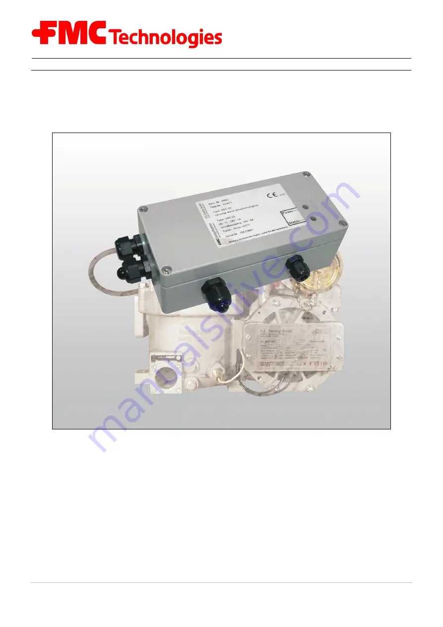
EPE2-Controller for Meter Draining System
EPE2
Installation Manual
Issue / Rev. 1.03 / JS / jp / March 2010
MN F08 003 US / DOK-450E
Sening®
Innovative Tank Truck Systems
Page 1: ...EPE2 Controller for Meter Draining System EPE2 Installation Manual Issue Rev 1 03 JS jp March 2010 MN F08 003 US DOK 450E Sening Innovative Tank Truck Systems ...
Page 2: ...ings Figure 4 Connection label in the device cover Drawing 61 351684 Drawing 61 351994 Chapter special service settings removed Appendix HyperTerminal terminal program settings removed Rev 1 03 March 2010 JS jp Release Minor changes Figure 5 Connection label in the device cover DIP switch S1 settings from MID version 3 50 Figure 3 Schematic structure Stand Alone Figure 4 Schematic structure with M...
Page 3: ...2 1 4 To make the job of the service personnel easier 12 2 2 Maintenance 12 3 Commissioning 13 3 1 Adaptation of the operating mode 13 3 1 1 Operating modes 14 3 1 1 1 Stand Alone residue discharge mode 14 3 1 1 2 MultiFlow residue discharge mode 14 3 2 Switching outputs in Stand Alone residue discharge operation 15 3 2 1 Switching output of the solenoid valve for the control air 15 3 2 2 Power Ou...
Page 4: ... the operating states 31 6 EPE2 Controller Technical data 33 7 Warranty and Service 35 8 Address and contact details 37 9 Indexes 39 9 1 Keyword index 39 9 2 Table of Figures 40 9 3 Index of Tables 40 Anhang A Drawings and Approvals 41 Drawings 42 E51 351677 Control unit residue discharge REC 1 42 E61 351684 EPE2 connection to residue discharge Stand Alone Standard 43 E61 351994 EPE2 connection to...
Page 5: ... This information is identified with suitable pictograms in the left margin to enable better distinction in context The following pictograms are used in this manual Danger sign Here Danger of explosions caused by easily flammable gases and liquids Working step Concrete action statements e g Press the Enter key Positive response message e g The main menu now appears Negative response message e g If...
Page 6: ... control air can then be omitted For this purpose the CAN bus connection to the MultiFlow truck computer is prepared The Stand Alone residue discharge or MultiFlow residue discharge modes are set via a DIP switch S1 on the REC 1S printed circuit board see also Figure 6 page 18 The EPE2 Controller consists of a sealed SVC 2S power supply unit and an REC 1S control board The use of the device is lim...
Page 7: ... 03 JS jp March 2010 7 1 3 Schematic Structure of GMVT 805 Stand Alone residue discharge Figure 3 Schematic structure of the device for discharging and refilling Stand Alone residue discharge The GMVT 805 with residue discharge system was only conceived for flow measurement of combustible liquids of Hazard Class AIII on tank trucks ...
Page 8: ...circuit causes blocking of the output signal to flow computer electronic me ter 12 and to the 3 2 way solenoid valve 21 The electronic meter 12 is used together with a mechanical measuring chamber for temperature compensated delivery of mineral oil products The above mentioned time relay is required that fluctuations of the liquid level in the sensing element causing measurement interruptions clos...
Page 9: ...ter Draining System EPE2 Installation Manual MN F08 003 US DOK 450E Rev 1 03 JS jp March 2010 9 1 4 Schematic Structure of GMVT 805 MultiFlow residue discharge Figure 4 Schematic structure of the device for discharging and refilling MultiFlow residue discharge ...
Page 10: ...EPE2 Controller is connected via a data bus directly with the MultiFlow electronic meter 12 The electronic MultiFlow meter takes over all control functions as per the EPE2 Hence the 3 2 way solenoid valve 21 of the switching devices is no longer needed If the type approved MultiFlow electronic meter together with the EPE2 Controller is used for control the 3 2 way solenoid valve 21 for the electri...
Page 11: ...cording to the circuit diagrams supplied The colours of the wires correspond to DIN 47100 Please follow the colour codes strictly The electrical installation must be carried out according to EN 60079 14 VDE 0165 No additional components must be added to the EPE2 housing since this would void the de vice approval 2 1 3 To ensure trouble free operation Disconnect the power supply during welding on t...
Page 12: ...y are easily accessible Even the electronic housings should be installed such that they are easily accessible Cables without plug in connectors may be shortened Slightly lubricate the fixing bolts of the covers prior to installation e g copper paste graphite grease This prevents the screws from corroding and ensures that you can loosen them after prolonged operation 2 2 Maintenance The EPE2 Contro...
Page 13: ...he Stand Alone residue discharge and MultiFlow residue discharge Both operating modes as well as other settings are made via the DIP switch S1 on the REC 1S printed circuit board see also Figure 6 page 18 The DIP switch S1 settings are shown in the following table DIP switch S1 on the REC 1S board MultiFlow residue discharge from MID version 5 00 1 ON With MultiFlow 2 OFF No Test 3 ON Only channel...
Page 14: ... termination resistors SVC 2S printed circuit board DIP switch S1 1 OFF termination resistors ON The switch has no effect on function in this operating mode The selected switch setting is thus arbitrary 3 1 1 2 MultiFlow residue discharge mode REC 1S printed circuit board DIP switch S1 1 ON In this operating mode control of the main air is made via the SeningTM MultiFlow The meter electronics need...
Page 15: ...e main air supply of the metering system is connected 3 2 1 Switching output of the solenoid valve for the control air The control air is switched off immediately after product shortage is detected The output is designed for the operation of solenoid valves with 12 volt control voltage with a max current of 430 mA order no MVS1 E11 12 3 2 2 Power Out switching output for the flow computer This out...
Page 16: ...w computer 24V out connec tion 3 4 Setting the sensor type The EPE2 Controller supports 3 types of sensors The selected switch or sensor is connected to the J3 input on the REC 1S control board The setting has to be made before commissioning via the jumpers Jp4 and Jp5 on the REC 1S printed circuit board listed in the following table The 3 sensor types have to be supplied with different voltages T...
Page 17: ...he DIP switch S1 3 has to be placed in the opposite position 3 5 Further tips for commissioning For the commissioning of the residue discharge it may be helpful if the switching output is continually switched independent of the input signals For this the DIP switch S1 2 on the power supply printed circuit board SVC 2S is to be set to the ON position The supply voltage 24 volts is thus always throu...
Page 18: ...450E 3 6 Components overview 3 6 1 Control board REC 1S Figure 6 Control board REC 1S 3 6 2 EPE2 Controller Internal overview SVC 2S power supply board REC 1S control board SVC 2S DIP switch S1 SVC 1S DIP switch S1 JP4 JP5 J1 solenoid valve connection J3 sensor connection J6 PC or Laptop Figure 7 EPE2 Controller Internal overview J3 sensor connection ...
Page 19: ... program version will activate printout of a receipt after residue removal 3 1 8 5 1 Residue removal control M 2 1 from version 5 00 1 Off 2 Stand alone Activates an instruction for residue removal in the event of product change 3 EPE2 manual As 2 however the wet leg sensor con nected to the EPE2 monitors the residue removal No restart of MultiFlow required after residue removal 4 EPE2 automatic A...
Page 20: ...ence After entering all the preset values and pressing the START key again the MultiFlow checks whether a product change has taken place be tween diesel and heating oil heating oil with ad ditives If this has happened a corresponding message is shown about the necessary residue removal If residue removal has not been carried out the driver must press the F2 key A corresponding entry is then made i...
Page 21: ...etected the corre sponding message is displayed Delivery in this case is not started until the measuring sys tem has undergone residue removal The MultiFlow does not need to be restarted in this case If parameter 3 1 8 5 1 is set to 4 it is also pos sible to control the residue removal from the measuring system from the MultiFlow using a residue removal pump A suitable pump must be connected to th...
Page 22: ...Inputs and Outputs In Menu 4 3 1 the diagnostic functions for the inputs and outputs including temperature and pulse sensors are summarised Diagnosis I O Menu 4 3 1 The status of the pulse inputs A and B must continually change between 0 and 1 when the pulse transmitter rotates In contrast the input PT must always be at 1 because 0 indicates a fault no sensor connected The temperature display cont...
Page 23: ...ay a functional test of the connected device solenoid valve is possible For safety reasons all outputs are set to 0 inactive on calling and on leaving the diagnostic screen The assignment of the outputs to functions depends on the selection of the valve control please refer to Parameter 3 1 8 1 and the respective circuit diagrams The current status of the valves must be observed without fail When ...
Page 24: ... interference no communication possible Node reference of operating device 3 8 2 1 Testing Links By pressing key F1 a general request broadcast will be sent to all nodes devices This request is to be answered within a few seconds Thus with this test function the linking status can be brought up to date While testing the links internal timeouts will occur so the display will need up to 10 sec for c...
Page 25: ...ic functions are compiled in menu 4 3 6 Diagnosis EPE2 Menü 4 3 6 The EPE2 is connected to the MultiFlow s external CAN bus A connection to the EPE2 via the CAN bus is required in order to control the EPE2 This connection can be made for test purposes using key 1 and or broken using key 3 The EPE2 has one output The status of this output can be changed during the test using key 2 The EPE2 also has...
Page 26: ...nosis IO Interface Menu 4 3 7 The eight outputs can be switched by pressing the corre sponding number 1 8 In the case of outputs allocated to a hose path in the configuration of the IO interface this is pos sible only when the electronic seal is broken The diagnostic function can be used only when the connection to the IO inter face is active On exiting the diagnostic screen the IO interface is re...
Page 27: ... 0 open 1 closed 2 interrupted 3 short circuited Press the F1 key to initiate an update of the overall status display Under normal circum stances this is not necessary however because all statuses are updated automatically as soon as they have been de tected by the MultiFlow There is a short delay between the change in status and the display updating due to the internal evaluation logic The diagno...
Page 28: ...EPE2 Controller for Meter Draining System EPE2 Installation Manual Sening Innovative Tank Truck Systems 28 Rev 1 03 JS jp March 2010 MN F08 003 US DOK 450E ...
Page 29: ... Power Out are switched on immediately The flow computer electronic meter is powered via the switch contact of the supply voltage relay In case of product shortage the float switch in the measuring system falls to dry and switches from full to empty Once the empty state is detected the solenoid valve in the main air is switched off and thus interrupts the discharge The flow computer is switched of...
Page 30: ...EPE2 Controller for Meter Draining System EPE2 Installation Manual Sening Innovative Tank Truck Systems 30 Rev 1 03 JS jp March 2010 MN F08 003 US DOK 450E ...
Page 31: ...ws the current switch status of the solenoid valve and the flow computer switching relay If the green Status LED lights continuously then the solenoid valve is powered and the flow computer switching relay has engaged If a product shortage is detected the green Status LED starts flashing for the time interval T1 The solenoid valve is now de energised and switched off If time T1 is elapsed the gree...
Page 32: ...EPE2 Controller for Meter Draining System EPE2 Installation Manual Sening Innovative Tank Truck Systems 32 Rev 1 03 JS jp March 2010 MN F08 003 US DOK 450E ...
Page 33: ... Power supply unit Type SVC 2S Input voltage 15V 28V 1A Outputs static 12V DC max total current 430 mA Outputs frequency 12V AC f 100Hz when connecting solenoid valves rated current consumption 400mA per solenoid valve Working temperature Tamb 20 C to 55 C Control unit Type REC 1S Input circuit Connection of sensors as per Namur level sensor Type NS2 Working temperature Tamb 20 C to 55 C ...
Page 34: ...EPE2 Controller for Meter Draining System EPE2 Installation Manual Sening Innovative Tank Truck Systems 34 Rev 1 03 JS jp March 2010 MN F08 003 US DOK 450E ...
Page 35: ...by abnormal ambient conditions in general damage due to external effects such as damage in shipment damage due to shock or im pact the effects of the weather or other natural phenomena 3 The right to claim under warranty becomes invalid if repairs or tampering have been carried out by persons not authorised by us for the work or if our devices have been fitted with sup plementary parts or accessor...
Page 36: ...EPE2 Controller for Meter Draining System EPE2 Installation Manual Sening Innovative Tank Truck Systems 36 Rev 1 03 JS jp March 2010 MN F08 003 US DOK 450E ...
Page 37: ...th the greatest care However the possibility of errors cannot be completely eliminated We are always very grateful for notification of any errors found Our service department will be happy to assist and can be contacted as follows Measurement Solutions F A Sening GmbH Regentstrasse 1 D 25474 Ellerbek Tel 49 0 4101 304 0 Zentrale Fax 49 0 4101 304 152 Service Fax 49 0 4101 304 133 Verkauf Fax 49 0 ...
Page 38: ...EPE2 Controller for Meter Draining System EPE2 Installation Manual Sening Innovative Tank Truck Systems 38 Rev 1 03 JS jp March 2010 MN F08 003 US DOK 450E ...
Page 39: ...51992 44 F Fixing screws 12 Float switch 29 flow computer 6 14 29 31 I Installation 11 22 J Junction boxes 12 M Main air feed 14 Main air supply 15 Maintenance 12 O operating mode 13 Operating modes 14 Operating States 31 P PG screw joints 11 Pictograms 5 Plug 11 Plug in connectors 12 product 20 Product changes 21 Product shortage 29 Pulse sensor 22 R REC 1S 14 Remote control 22 Residue discharge ...
Page 40: ...for discharging and refilling Stand Alone residue discharge 7 Figure 4 Schematic structure of the device for discharging and refilling MultiFlow residue discharge 9 Figure 5 Connection label in the device cover 15 Figure 6 Control board REC 1S 18 Figure 7 EPE2 Controller Internal overview 18 Figure 8 Residue discharge function 29 9 3 Index of Tables Table 1 DIP switch S1 settings 13 Table 2 Sensor...
Page 41: ...v 1 03 JS jp March 2010 41 Anhang A Drawings and Approvals Drawings No Page Control unit residue discharge REC 1 E51 351677 42 EPE2 connection to residue discharge Stand Alone Standard E61 351684 43 EPE2 connection to residue discharge with MultiFlow E61 351994 44 Approvals No Page EC Declaration of Conformity EMV 2004 108 EG 45 ...
Page 42: ...42 Rev 1 03 JS jp März 2010 MN F08 003 US DOK 450E Drawings E51 351677 Control unit residue discharge REC 1 ...
Page 43: ...MN F08 003 US DOK 450E Rev 1 03 JS jp März 2010 43 E61 351684 EPE2 connection to residue discharge Stand Alone Standard ...
Page 44: ...44 Rev 1 03 JS jp März 2010 MN F08 003 US DOK 450E E61 351994 EPE2 connection to residue discharge with MultiFlow ...
Page 45: ...MN F08 003 US DOK 450E Rev 1 03 JS jp März 2010 45 Approvals EC Declaration of Conformity ...
Page 46: ...46 Rev 1 03 JS jp März 2010 MN F08 003 US DOK 450E ...
Page 47: ......
Page 48: ...sberg Norway 47 32 286 700 Buenos Aires Argentina 54 11 4312 4736 Integrated Measurement Systems Corpus Christi TX USA 1 361 289 3400 Kongsberg Norway 47 32 286 700 San Juan Puerto Rico 1809 787 274 3760 United Arab Emirates Dubai 971 4 331 3646 Liquid Measurement Products Erie PA USA 1 814 898 5000 Los Angeles CA USA 1 310 328 1236 Slough England 44 1753 57 1515 Ellerbek Germany 49 4101 304 0 Bar...