background image

13

This equipment has been tested and found to comply with the limits for a Class B digital device pursuant to part 
15 of the FCC rules. These limits are designed to provide reasonable protection against harmful interference in a 
residential installation. This equipment generates, uses and can radiate radio frequency energy and, if not installed 
and used in accordance with the instructions, may cause harmful interference to radio communications. However, 
there is no guarantee that interference will not occur in a particular installation. If this equipment does cause 
harmful interference to radio or televison reception, which can be determined by turning the equipment off and on, 
the user is encouraged to try to correct the interference by one or more of the following measures:

•  Reorient or relocate the receiving antenna.
•  Increase the separation between the equipment and receiver.
•  Connect the equipment into an outlet on a circuit different from that to which the receiver is connected.
•  Consult the dealer or an experienced radio/TV technician for help.

To assure continued compliance, any changes or modifications not expressly approved by the party responsible for 
compliance could void the user's authority to operate this equipment. 

This equipment complies with Part 15 of the FCC Rules. Operation is subject to the following two conditions:
(1) This device may not cause harmful interference.and (2) This device must accept any interference received, 

including interference that may cause undesired operation.

Caution!
The manufacturer is not responsible for any radio or TV interference caused by unauthorized modifications to this 
equipment. Such modifications could void the user authority to operate the equipment.
1.  The antenna(s) used for this transmitter must be installed to provide a separation distance of at least 20 cm 

from all persons and must not be co-lacated or operating in conjunction with any other transmitter.End-users 

and installers must be provided with antenna installation instructions and transmitter operating conditions for 

satisfying RF exposure compliance.

2.  Move all your channels to the desired position.
3.  Select [All channels] and then [Yes] in the confirmation box. 

8. Certifications 

8.1 DoC Declaration

8.2 CE Warning

The antenna(s) used for this transmitter must be installed to provide a separation distance of at least 20 cm from all 
persons and must not be co-located or operating in conjunction with any other transmitter. End-users and installers 
must be provided with antenna installation instructions and transmitter operating conditions for satisfying RF 
exposure compliance.

8.3 

Appendix 1 FCC Statement 

Hereby, [Flysky Technology co., ltd] declares that the Radio Equipment [FS-G4P-BS] is in compliance with RED 
2014/53/EU.
The full text of the EU DoC is available at the following internet address: www.flysky-cn.com.

Summary of Contents for FS-G4P-BS

Page 1: ...Copyright 2021 Flysky Technology co ltd USER MANUAL USER MANUAL Digital Proportional Radio Control System This product is only for 15 years old or above FS G4P BS...

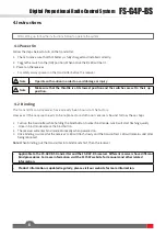
Page 2: ...nal safety as well as the safety of your equipment If you encounter any problems during using please refer to this manual first If the problem is still not resolved please contact the local dealer dir...

Page 3: ...1 Power On 6 4 2 Binding 6 4 3 Stick Calibration 7 4 4 Power Off 7 5 System Functions 8 5 1 Channel Description 8 5 2 Channel Reverse 8 5 3 Trims 8 5 4 D R 9 5 5 Mode switching 9 5 6 Failsafe 9 5 7 Be...

Page 4: ...y of you and others do not operate in the following places Near any site where other radio control activity may occur Near power lines or communication broadcasting antennas Near people or roads On an...

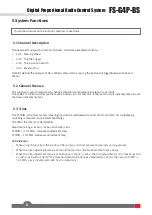
Page 5: ...uction The FS G4P BS is a simple 4 channel transmitter using the latest 2 4GHz 2A BS Automatic Frequency Hopping Digital System Designed to be sleek passionate and powerful for entry level enthusiasts...

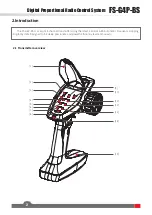
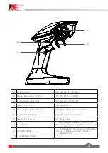
Page 6: ...ndicator green LED G LED 15 Base 4 AA battery compartment 6 Throttle Trim TH TRIM 16 Three position switch CH3 7 Steering D R ST D R 17 Button CH4 8 Power Switch 18 Wheel Angle the maximum rotation of...

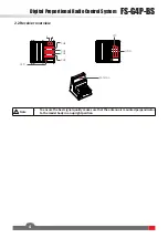
Page 7: ...ortional Radio Control System 4 2 2 Receiver overview CH4 CH3 CH2 CH1 LED Antenna Note To ensure the best signal quality make sure that the antenna is mounted perpendicular to the model body in an upr...

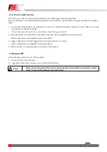
Page 8: ...to excessive heat or liquids Danger Do not drop the battery or expose to strong shocks or vibrations Danger Always store the battery in a cool dry place Danger Do not use the battery if damaged Batter...

Page 9: ...ind button 2 The receiver will enter bind mode atomically when powered on 3 Once binding is successful the receiver s LED will flash slowly and the transmitter s LED will remain solid after being rebo...

Page 10: ...ing and on off 2 Calibrate wheel Turn the wheel completely clockwise then completely counterclockwise When calibration is completed the R LED will be off 3 Trigger calibration Pull the trigger back th...

Page 11: ...s up it indicates reverse and the down indicates normal The ST TRIM is the trims for CH1 steering and can be multiplexed as trims of CH3 and CH4 For multiplexing switching mode refer to 5 5 Mode Switc...

Page 12: ...default setting when powering on is mode 1 Mode 1 G LED flashes slowly once ST TRIM is CH1 trim adjustment ST D R is servo travel adjustment Mode 2 G LED flashes twice slowly ST TRIM is CH1 trim adju...

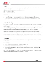
Page 13: ...to 1250 1500 1750us Function settings To switch between beginner and normal modes press and hold the CH4 button while turning the steering wheel completely counterclockwise as far as it can and at th...

Page 14: ...Bm e i r p EU 2 4GHz Protocol 2A BS Distance 300m Ground Channel Resolution 1024 Battery 6V DC 1 5AA 4 Charging Interface NO Life time According to battery type Low Voltage Warning 4 2V Antenna Type B...

Page 15: ...FS G4P BS Digital Proportional Radio Control System 12 7 Package Contents Transmitter 1 FS G4P BS Receiver 1 FS R4P BS...

Page 16: ...lowing two conditions 1 This device may not cause harmful interference and 2 This device must accept any interference received including interference that may cause undesired operation Caution The man...

Page 17: ...hat comply with Innovation Science and Economic Development Canada s licence exempt RSS s Operation is subject to the following two conditions 1 This device may not cause interference 2 This device mu...

Page 18: ...pyright 2021 Flysky Technology co ltd www flysky cn com Release date 2021 10 23 CE FCC ID N4ZG4P00 Manufacturer FLYSKYTechnologyCo Ltd Address 16F HuafengBuilding 6006ShennanRoad FutianDistrict Shenzh...

Reviews: