background image

ECLIPSE

–RIDER    USER  MANUAL__ _____________                                                 ___           VER.  1.1


      Pag. 28 


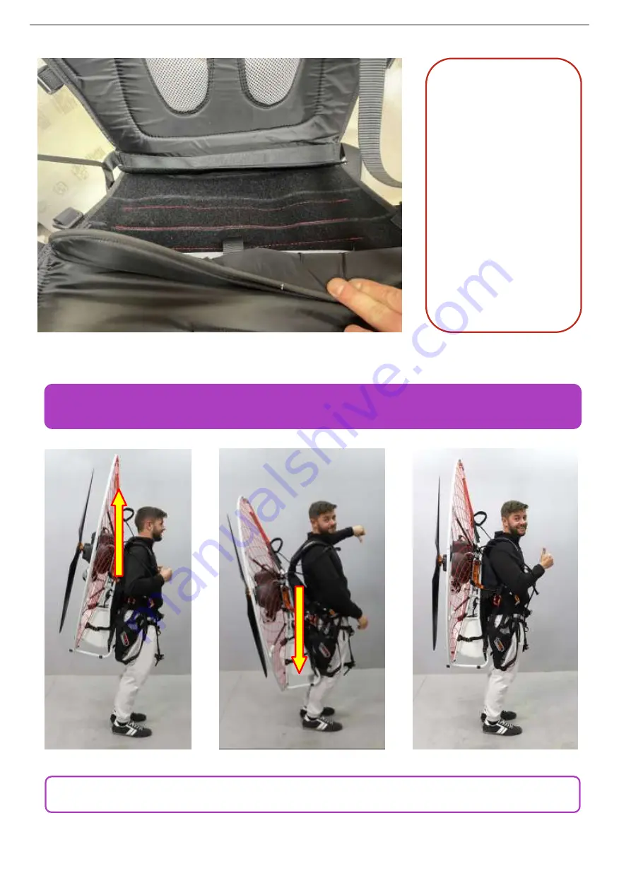
Adjust the vertical position of the paramotor on the shoulders.


OPTIMAL ADJUSTMENTS


It is possible 

 to adjust  

the depth 

of the seat


blocking it 

in the desired 

position 

on the prepared 

velcro. 

Summary of Contents for ECLIPSE-RIDER

Page 1: ...VER 1 1 ENG Copyright by FLY Products s r l Via Per n 30 63066 GROTTAMMARE AP ITALY Tel 39 735 632486 www flyproducts com fly flyproducts com...

Page 2: ...ECLIPSE RIDER USER MANUAL__ _____________ ___ VER 1 1 Pag 2...

Page 3: ...ECLIPSE RIDER USER MANUAL_____________ ___ VER 1 1 Copyright FLY Products s r l Pag 3 USER MANUAL FRAME PAG 6 HARNESS PAG 22 SETTINGS PAG 28 PROPELLER PAG 39 HANDGRIP PAG 40 WARRANTY PAG 41...

Page 4: ...ce must be met Because of the inherent risks in flying any Paramotor no warranty of any kind can be made against equipment failures accidents and even fatal injuries This Paramotor is not covered by p...

Page 5: ...6 RIDER PROPELLER 140 MONO RIM 153 60 2 153 60 2 RIDER PROPELLER 140 DOUBLE RIM 155 61 0 155 61 0 Note central frame RIDER can fit all RIDER configurations mono double rim for 130 cm 51 1 in propeller...

Page 6: ...sed down until doing a slight pull and rotation until the hole is released from the button thus allowing the separation of the two parts The supports of the cage to be mounted on the central frame are...

Page 7: ...support To start Insert the starter support D on the central engine frame first 1 Hook the starting pulley on the starter support as shown in the figure 2 Insert the LONG A rods in the central frame...

Page 8: ...ht and left into the SHORT rods C by slightly forcing the rods upwards 1 2 3 4 5 4 5 1 Thread the two upper parts of the cage without joining them together the connection will be made after inserting...

Page 9: ...d proceed to the lower RIGHT and LEFT coupling checking that the sealing button has come out correctly from its hole and the part is actually locked Then proceed to the RIGHT and LEFT lateral connecti...

Page 10: ...l you have the maximum tension of the net Lock the velcro in correct position by pressing it on the underlying loop 10 Connect the two upper semicircles together always checking that the sealing butto...

Page 11: ...to ensure complete matching Finally join the lower plastic buckles to fix and perfectly stretch the net Hook the parts making sure the buckle is perfectly sealed Lock the coupling by moving the butto...

Page 12: ...ng to force some parts too much and avoid possible damage we recommend proceeding with the following sequence of operations CAGE DISASSEMBLY 1 2 3 4 Start by unlocking the safety of the lower plastic...

Page 13: ...taking care to close the velcros on itself 5 5 6 7 8 Uncouple the upper cage from the lower one by pressing the push pin button and pulling the upper part upwards Repeat the operation on the other si...

Page 14: ...11 Unhook the lower cage by pressing the push pin button and pulling the part outwards Repeat the operation on the other side 10 5 11 5 12 13 Slide the lower cage out of the rods while holding them f...

Page 15: ...from the rods holding them firmly in place Repeat the operation on the other side 16 Join together the two plastic buckles of the disassembled net below 14 5 15 5 16 5 17 5 17 Lift the two lower semi...

Page 16: ...wo semicircles from the rods and fold everything in a booklet so that the cage is ready and folded in the correct way to put it back in its bag 18 5 19 5 STORAGE OF THE CAGE Place the rods in the spec...

Page 17: ...sembly and disassembly operations of the single rim frame of the RIDER series are identical to the ECLIPSE frame therefore it is advisable to follow the procedure explained above RIDER SINGLE RIM FRAM...

Page 18: ...D from each other taking care to insert points 4 AT THE SAME TIME and finally again at the same time points 5 making sure the snap pins are perfectly inserted When all the parts are in place you can p...

Page 19: ...to prevent they stick to the net in the subsequent operations detach all the joints of the outer rim starting from points A B and continue with points C D E Then following the order illustrated above...

Page 20: ...NUAL__ _____________ ___ VER 1 1 Pag 20 Turn the strap around the tube between the two velcroes and close them to stop it Place the tank in the correct position onto its supports and lock it as shown...

Page 21: ...ducts s r l Pag 21 Pass the belt inside the red eyelet close it and lock it with the safety belt S as shown in the photo To release the tank open the safety little belt S detach the velcro from the cl...

Page 22: ...harness by hooking it to the central frame using the two upper straps which have TWO different colored indicators to adapt it to the different sizes as shown in the photo ECLIPSE HARNESS ASSEMBLY AND...

Page 23: ...aps away stopping them under the loops as shown in the photo Hook the middle side straps of the harness having as a reference the red seam as shown in the photo Hook the lower harness anchoring straps...

Page 24: ...ms in position and taking care to line the holes lock them with the push pins keeping the button pressed and releasing it only after it has completely entered ATTENTION When mount the pivot arms alway...

Page 25: ...ight FLY Products s r l Pag 25 It is possible to adjust the seat deep by removing or adding the extension blocking it on the prepared velcro To avoid possible entanglement when disassembling the pivot...

Page 26: ...n the prepared plate and lock the push pin Hook the four lower straps onto the quick lock provided bucklets For a correct use of the push pin keep the button pressed while it is slipping and while clo...

Page 27: ...Products s r l Pag 27 Hook the elastic rope of the starter handle to the prepared eyelet and lock it under the velcro for 5 10 cm 2 4 In Put the pivotarms in position and taking care to keep the holes...

Page 28: ...__ _____________ ___ VER 1 1 Pag 28 Adjust the vertical position of the paramotor on the shoulders OPTIMAL ADJUSTMENTS It is possible to adjust the depth of the seat blocking it in the desired positio...

Page 29: ...eoff run Adjustments are very important for safety and comfort Test the position before making the first flight Hang the paramotor and check the inclination that must be between 25 and 30 Check that y...

Page 30: ...ilot size 3 Torque generated by the propeller rotation PIVOT ARMS ADJUSTEMENTS The first rule to be observed is the position of the attachments according to the direction of the fixing screws The bolt...

Page 31: ...versa Pilot weight adjustment it is obtained by moving the point of attachment of the paraglider of one or more holes forward for heavy pilots or back for light riders like this scheme Each displaceme...

Page 32: ...optimal position of the paramotor in the simulator is between 25 and 30 degrees in flight the trim will compensate for the propeller thrust depends on the engine power and weights Pilot size adjustme...

Page 33: ...n engines with BELT reduction such as MOSTER CLOCKWISE in engines with MECHANICAL reduction such as ATOM 80 THOR For size XS extra small or to lift the seat you can move backwards the front support B...

Page 34: ...NUAL__ _____________ ___ VER 1 1 Pag 34 To correctly assemble the paraglider coupling belt first insert the end C in the loop of the belt hooked to the shackle and then pass the entire belt from the A...

Page 35: ...ECLIPSE RIDER USER MANUAL_____________ ___ VER 1 1 Copyright FLY Products s r l Pag 35 Tighten the low anchor C well then proceed by inserting the end A upwards coming out of the support D...

Page 36: ...L__ _____________ ___ VER 1 1 Pag 36 This operation performed on both sides ends assembly of the pivot arms ASCEVO To finish the assembly pass the end A in the Loop B pull hard to free the Loop A to w...

Page 37: ..._____________ ___ VER 1 1 Copyright FLY Products s r l Pag 37 To further increase the anti torque effect the A belt can be inserted from the external side of the attachment effectively shifting the pa...

Page 38: ...____________ ___ VER 1 1 Pag 38 WARNING Do not over tighten these nuts to avoid weakening the structure and therefore the seal Preferably use a torque wrench calibrated at 10 N m Newton meter which co...

Page 39: ...direction of the blades Propeller mounting on motors with BELT reduction COUNTERCLOCKWISE ROTATION for the MOSTER engine Propeller mounting on motors with mechanical reduction CLOCKWISE ROTATION for t...

Page 40: ...IPSE RIDER USER MANUAL__ _____________ ___ VER 1 1 Pag 40 MULTIFUNCTIONAL HANDLE THROTTLE CONTROL LEVER START ENGINE BUTTON only on electric starter engines with VELCRO HAND TIGHTENING STOP ENGINE BUT...

Page 41: ...Purchaser or any other person for any loss or damage whether direct or indirect or consequential or incidental including without limitation any damages or claims by third parties caused by defective...

Page 42: ...ECLIPSE RIDER USER MANUAL__ _____________ ___ VER 1 1 Pag 42 NOTE...

Page 43: ...DER USER MANUAL_____________ ___ VER 1 1 Copyright FLY Products s r l Pag 43 Copyright by FLY Products s r l Via Per n 30 63066 GROTTAMMARE AP ITALY tel fax 39 735 632486 www flyproducts com fly flypr...

Reviews:

Related manuals for ECLIPSE-RIDER