background image

OPERATING INSTRUCTIONS


28                                                                                          

Side channel blower

Version: 27222 - C

Schmalenberger GmbH + Co. KG 

D-72072 Tübingen / Germany

7

Maintenance / repair

7.1

General information

The  operator  must  ensure  that  all  inspection,  maintenance  and  repair  work  on  the  side
channel  blower  is  performed  only  by  authorised  and  specially  trained  personnel.  The
operator  must  ensure  that  personnel  is  sufficiently  informed  thorough  study  of  the
Operator's Manual. 
We  recommend  creating  and  following  a  maintenance  plan.  This  will  help  you  to  avoid
costly repairs and achieve problem-free and reliable operation of the side channel blower.
Only original spare parts may be used for repairs. 
When  working  on  the  motor,  the  instructions  of  the  relevant  motor  manufacturer  and
instructions must be followed.

7.2

Maintenance / inspection

The  following  information  should  be  used  to  create  a  maintenance  plan.  It  consists  of
minimum  recommendations  that  must  be  adjusted  and  if  necessary  supplemented  as
required by local specific details of how the side channel blower is used.

7.2.1

Checks

Continuous checks:

Delivery data for the side channel blower (pressure, quantity)

Current consumption

Daily checks:

Running = quiet with no vibration

Storage temperature

Check / replace every 6 months:

Check if screws are tight.

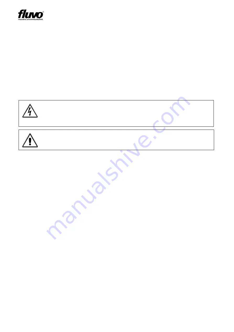
Caution - danger of death! 
Normally  work  on  terminal  boxes  and  on  machine  control  must  only  be
performed with the electrical connections unclamped or the power turned off to
avoid electrical shocks.

Danger of injury and death!
During checks and maintenance work, secure the side channel blower against
being turned on unintentionally (turn off the power).

Summary of Contents for 27222-C

Page 1: ...Side channel blower Operator s Manual Translation of the Original 27222 C GB ...

Page 2: ...Schmalenberger GmbH Co KG D 72072 Tübingen Germany SKV Version 27222 C 2 ...

Page 3: ...de la CE EC Directives Normativas de la CE Direttive CE 2006 42 EC 2006 95 EC 2004 108 EC Zur sachgerechten Umsetzung der in der EG Richtlinie genannten Sicherheits und Gesundheitsanforderungen wurde n folgende Norm en herangezogen Pour mettre en partique dans les règles de l art les prescritions en matière de sécurité et de santé stipulées dans les Directives de la CE il a été tenu compte de la d...

Page 4: ...ntenance and repair work 13 2 9 Potential sources of danger from the side channel blower 13 3 Transport storage and assembly 15 3 1 Transport and storage 15 3 1 1 Transport 15 3 1 2 Storage 16 3 1 3 Preservation 16 3 2 Unpacking cleaning and assembly 17 3 2 1 Unpacking 17 3 2 2 Cleaning 17 3 2 3 Assembly 17 3 3 Setting up and connecting 17 3 3 1 Before starting to set up check the following 18 3 3...

Page 5: ...ir 29 7 3 1 General information 29 7 3 2 Preparations for disassembly 29 7 3 3 Disassembly removal of the side channel blower 29 7 3 4 Disassembly dismantling the side channel blower 30 8 Spare parts list drawing 31 9 Appendix 34 9 1 Decommissioning placing in storage preservation 34 9 1 1 Placing new side channel blowers in storage 34 9 1 2 Recommissioning after being placed in storage 34 9 2 Dis...

Page 6: ...tions helps to avoid dangers avoid repair costs and downtimes and increase the reliability and service life of the side channel blower The Operator s Manual does not take into consideration requirements for specific location The operator is responsible for observing these requirements The nameplate indicates the series and frame size the most important operating data and the factory number Please ...

Page 7: ... 8 Power output 4 Frequency protection type 9 Delivery pressure 5 Item number The blower nameplate Fig 2 shows an example is located on the fan hood of the blower Fig 3 Motor nameplate 1 Blower type 4 Frequency speed 2 Motor protection type heat class5 Voltage current 3 Power output Power factor The motor nameplate Fig 3 shows an example is located on the electric motor 1 2 3 4 5 6 7 8 9 1 2 3 4 5...

Page 8: ... 20 C The side channel blower is not suitable for setting up in a potentially explosive atmosphere If the side channel blower will be used for any purpose other than what is prescribed in the specification always consult with the manufacturer We will be pleased to determine what adjustments would be required for the new intended use Conversions and changes to the side channel blower are not permit...

Page 9: ... blower It is the side channel blower s birth certificate and must be treated as such The confirmation of order together with the delivery slip can be used as a replacement for proof of technical data Blower type SKV 45 SKV 105 SKV 135 SKV 255 SKV 360 SKV 600 Output 0 95 kW 1 2 kW 2 3 kW 2 9 kW 5 5 kW 7 0 kW Voltage 230 400 V 230 400 V 230 400 V 230 400 V 400 V 400 V Frequency 50 Hz 50 Hz 50 Hz 50...

Page 10: ...ers and observe all the instructions of this Operator s Manual Eliminate all malfunctions that could have a detrimental effect on safety immediately 2 2 Signs and symbols We warn you of sources of danger in this Operator s Manual through corresponding notices The use of symbols is designed to direct your attention at these notices Notices placed directly on the side channel blower such as the arro...

Page 11: ...a shaft the shaft must have sufficient ventilation motor cooling 2 5 Safety instructions for connection Electrical equipment must only be installed and serviced by qualified personnel Applicable safety regulations and equipment requirements at the installation site must be observed The term qualified professional Fachkraft is defined in VDE 0105 and IEC364 This Operator s Manual does not contain a...

Page 12: ...h the suction opening open The open suction opening must be covered with a protective grating in accordance with DIN EN 294 Do not reach into the suction opening Caution risk of injury Very strong blowing effect on the blowing connection Objects that are drawn in may be forcibly ejected at high speed The side channel blower is intended exclusively for conveying clean air Foreign objects or impurit...

Page 13: ...rty may arise during use A residual risk still remains Potential danger zones of the side channel blower are the suction connection the blowing connection the blower housing Danger of entanglement A powerful suction effect is present on the suction connection Danger of impact Objects which have been drawn in may be forcibly ejected at high speed Caution risk of injury Make certain to wear close fi...

Page 14: ...t access Electrical equipment Caution risk of injury Protect the user from contact with the side channel blower Install a guard to prevent contact Allow the side channel blower to cool off before starting maintenance and repair work Caution Electrical voltage Work on the side channel blower must only be performed by properly trained and qualified professionals and must be performed in accordance w...

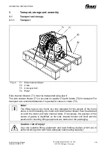
Page 15: ...ort over extended distances it is packed in cases or crates T2 Note The lifting lugs on the motor are only designed for the weight of the motor alone A unit consisting of a motor and side channel blower must be attached on both the motor and side channel sides If necessary the position of the centre of gravity is identified on the side channel blower unit itself and the positions for inserting lif...

Page 16: ...ust be filled with oil Storage for extended duration If the storage time exceeds 2 years the roller bearings in the motor must be regreased or completely replaced 3 1 3 Preservation The side channel blowers we deliver are provided with preservation according to the storage time specified in the order This preservation must be removed before commissioning see Section 3 2 2 Cleaning If the side chan...

Page 17: ... is therefore ready for delivery 3 3 Setting up and connecting Note If possible do not use steam jet cleaners If you do make certain not to damage the electric motor and bearings during use Note Check to ensure the side channel blower is running easily and freely before starting assembly Other external accessories such as air chambers etc that are not premounted on the side channel blower in the f...

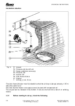
Page 18: ...Pressure end P5 Suction end P6 Side channel blower P7 Pipeline Y Air loop y min 50 cm The side channel blower must be installed so that the air loop is always at least y 0 5 m above the water level One side channel blower can supply several air pads with compressed air The air pad can be installed in the bottom It can also be built into a bench or reclining recess 3 3 1 Before starting to set up c...

Page 19: ...nel blower Lay pipelines continuously falling for the supply to prevent air lock from forming Depending on the type of system and side channel blower installation of backflow prevention valves and shut off elements is recommended Expansion of pipelines due to temperature must be countered by suitable measures We recommend installing compensators directly between the side channel blower and the pip...

Page 20: ...n out with air Often welding beads pipe scale and other impurities do not come loose until some time has passed They must be kept out of the pipe by installing a sieve in the suction line of the side channel blower The open cross section of the sieve must be at least three times the cross section of the pipeline to prevent too much resistance from building up due to trapped foreign objects Experie...

Page 21: ...ential bonding with a cross section of 10 mm must be applied on the connection terminal so identified on the motor mount or next to the terminal box Compare the existing mains power supply with the information on the motor nameplate Section 1 1 User information and select a suitable circuit We recommend using a motor protection device Motors with explosion protection increased safety Ex e temperat...

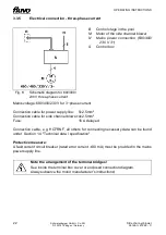
Page 22: ...rs for connecting necessary data can be found under Section 1 4 Technical data specification Protective measure A fault current circuit breaker rated error current 30 mA must be provided in the mains power supply line Fig 6 Schematic diagram for 690 400 230 V three phase current B Control stage in the pool M Motor of the side channel blower N Mains power connection 690 400 230 V 3 S Control box No...

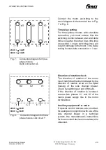
Page 23: ...ting for star delta connection 3 sec Fig 8 Connection diagram for three phase motors star circuit Y Direction of rotation check The direction of rotation of the motor must match the direction indicated by the direction of rotation arrow on the spiral housing of the side channel blower Check by switching on and off briefly If the direction of rotation is incorrect reverse two phases L1 and L3 of th...

Page 24: ...ain the following preconditions are met before initial commissioning of the side channel blower 1 The side channel blower is connected electrically with all protective devices in accordance with requirements 2 Rotating parts of the side channel blower must be provided with a contact safety device In accordance with the accident prevention requirements UVV the side channel blower may only be operat...

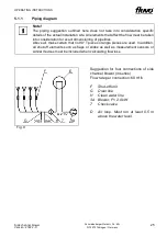
Page 25: ...eration for exact dimensioning of pipelines Above all make certain that no 90 T pieces or angle pieces are used In addition all shut off elements such as flaps or slides as well as measurement sensors or similar devices must be included when calculating flow loss Fig 9 Suggestion for four connections of side channel blower in series Flow rate per connection 60 m h F Shut off unit G Drain line H Cl...

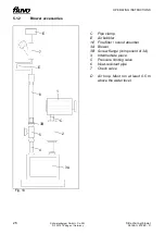
Page 26: ...n Germany 5 1 2 Blower accessories Fig 10 C Pipe clamp E Air bubbler 1 2 Fine filter sound absorber 3A Blower 3B Screw flange component of 3A 4 Intermediate piece 5 Pressure limiting valve 6 Heat resistant pipe 7 Check valve D Air loop Must run at least 0 5 m above the water level E 7 6 5 4 3B E 1 2 C 3A ...

Page 27: ...rature or in any case 90 C measured on the outside of the motor housing When the side channel blower is in operation the shut off element is not closed in the supply line 6 1 1 Faults When faults occur while the side channel blower is in operation that are not caused by the control system or other external errors follow these steps 1 Pinpoint the fault or malfunction 2 Determine the cause 3 Elimin...

Page 28: ...elevant motor manufacturer and instructions must be followed 7 2 Maintenance inspection The following information should be used to create a maintenance plan It consists of minimum recommendations that must be adjusted and if necessary supplemented as required by local specific details of how the side channel blower is used 7 2 1 Checks Continuous checks Delivery data for the side channel blower p...

Page 29: ...wer Check the individual parts for wear and damage Parts that are not in flawless condition must be reworked or replaced 7 3 2 Preparations for disassembly Before starting disassembly the side channel blower must be secured so that it cannot be turned on turn the power off Place a warning notice on the switch cabinet If the system is in operation inform the shift manager When performing the jobs d...

Page 30: ...ch the side channel blower or the version of if that you have or that damaged parts which may still be discovered can be obtained in short order that you have all tools and auxiliary equipment required for work Note Use only original spare parts for repairs Observing these instructions is a precondition for problem free operation of the side channel blower and for honouring any warranty claims tha...

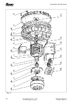
Page 31: ...lower Version 27222 C Schmalenberger GmbH Co KG D 72072 Tübingen Germany 8 Spare parts list drawing The exploded drawing appears on the next page The following section is the spare parts list for your side channel blower Please note your type ...

Page 32: ...OPERATING INSTRUCTIONS 32 Side channel blower Version 27222 C Schmalenberger GmbH Co KG D 72072 Tübingen Germany Fig 11 ...

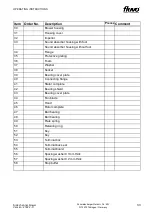
Page 33: ... absorber housing without foot 34 Flange 35 Protective grating 36 Foam 37 Washer 38 Socket 39 Bearing cover plate 40 Connecting flange 41 Stator complete 42 Bearing shield 43 Bearing cover plate 44 Fan blade 45 Hood 46 Rotor complete 47 Ball bearing 48 Ball bearing 49 Plate spring 50 Retaining ring 51 Key 52 Key 53 Terminal box 54 Terminal box seal 55 Terminal board 56 Spacing washer 0 1mm thick 5...

Page 34: ...e Removal of preservation Before the side channel blower that was in storage is installed the preservation material with which it was coated and or filled must be removed To do this follow the instructions in Section 3 2 2 Cleaning Recommissioning Reinstall the previously removed side channel blower as described in Section 3 3 Setting up and connecting Immediately after work is complete all safety...

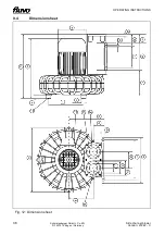
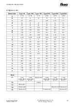
Page 35: ...to shut down the side channel blower permanently and take it out of operation observe local regulations for disposal of industrial waste 9 3 Documents for operation The following documents are enclosed Operator s Manual Dimensional diagram For complaints related to the side channel blower motor please contact us or the motor manufacturer ...

Page 36: ...OPERATING INSTRUCTIONS 36 Side channel blower Version 27222 C Schmalenberger GmbH Co KG D 72072 Tübingen Germany 9 4 Dimension sheet Fig 12 Dimension sheet ...

Page 37: ...280 ø 204 ø 328 ø 345 ø 390 k 17 17 17 20 20 25 l 333 345 383 437 472 559 m 358 420 435 505 530 695 n 196 225 225 260 282 325 o 60 80 80 85 85 95 p 12 12 12 18 18 20 q 90 125 125 145 145 160 r 220 300 365 365 400 s 250 350 350 420 420 450 t 44 5 55 55 65 65 80 u ø 68 ø 85 ø 85 ø 110 ø 110 ø 118 v 79 100 100 130 130 145 w 136 145 145 175 197 230 x 358 386 396 460 500 560 Item 11 3 stop buffers offs...

Page 38: ...l information from the specification or confirmation of order You will find the side channel blower number on the blower nameplate which is fastened onto the fan hood of the motor The confirmation of order or motor number may also be helpful This will help us deliver the right spare part for your side channel blower Customer Service Schmalenberger offers a 24 hour service for spare parts delivery ...

Page 39: ...39 Side channel blower Version 27222 C Schmalenberger GmbH Co KG D 72072 Tübingen Germany ...

Page 40: ...trömungstechnologie Fax 49 0 7071 70 08 10 Im Schelmen 9 11 Internet www fluvo de D 72072 Tübingen Germany E mail info schmalenberger de 2017 Schmalenberger GmbH Co KG All rights reserved Manual is subject to changes Side channel blower Version 27222 C ...

Reviews: