Fluke ScopeMeter 192 User'S Manual Supplement Download Page 12

Fluke 192/196/199
User Manual

2-6

Persistence

Use persistence to select the display time of the upper and
lower boundaries of dynamic waveforms.  Use persistence
also to display color modulation and color burst shapes.

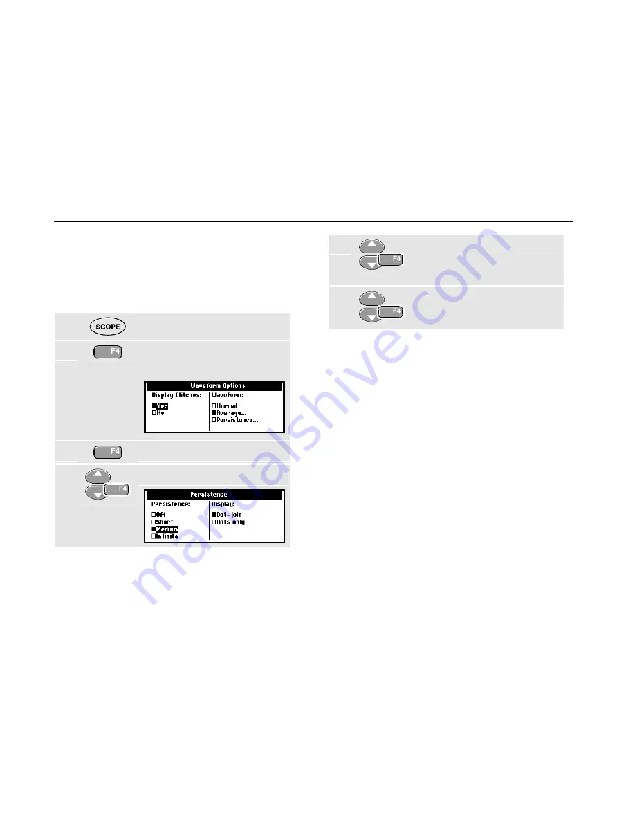
To select persistence, do the following:

1

Display the 

SCOPE 

key labels.

2

Open the Waveform Options
menu.

3

Jump to the Waveform field.

4

Open the Persistence  menu

5

Select one of the persistence
options and jump to Display

6

Select Dot-join or Dots only.
Accept the selection and close
the menu.

Dot join

The choice between Dot-join or Dots only depends on
your personal preference for the waveform representation
on screen, or in documentation.

Summary of Contents for ScopeMeter 192

Page 1: ...uke Corporation All rights reserved Printed in the Netherlands All product names are trademarks of their respective companies Fluke 192 196 199 MS 190 and MA 190 Users Manual Supplement Fluke 199 Scop...

Page 2: ...itation of Liability 1 1 About the MS 190 1 2 Factory Installed MS 190 1 2 MS 190 Package for Field Installation 1 2 MA 190 Accessory Kit 1 4 2 Using the MS190 Function 2 1 mAs Measurements 2 1 Extend...

Page 3: ...k use only and do not comply with the voltage rating on most other ScopeMeter accessories Carefully read the warning below which is an explicit addition to the general accessory and ScopeMeter safety...

Page 4: ...the type plate shows the text MS 190 Installed as shown in the figure below The contents of the shipment includes the ScopeMeter Test Tool kit provided with the MS 190 software extension For the conte...

Page 5: ...ation instructions Prior to installation you must register at our internet site www Fluke com ScopeMeter Requirements Fluke 192 196 199 ScopeMeter with software version V03 00 or higher Note Earlier v...

Page 6: ...ed through terminator for additional dynamic range and offset See Fig 1 1 CS 190 1R 1 Ohm current shunt for sensitive current and mAs measurements Max 500 mA See Fig 2 1 Safety designed 50 Ohm BNC cab...

Page 7: ...eforms HOLD recorded waveforms and on saved waveforms To perform mAs measurements do the following 1 Connect the current shunt CS190 1R to input A using the BNC cable see Figure 2 1 2 Connect the curr...

Page 8: ...key labels 6 Open the Probe on A menu 7 Select Current with the arrow keys then press ENTER to jump to Sensitivity 8 Select for example 1 V A with the arrow keys then accept 9 Display the cursor key l...

Page 9: ...sition on the waveform 14 Highlight the right cursor 15 Move the right cursor to the desired position on the waveform Extended Offset The MS190 extended offset function enlarges the vertical trace pos...

Page 10: ...hin the dynamic range just as with any Oscilloscope The dynamic range limits are the same as the trace offset limits given in the section Specifications below In practice you must take care when using...

Page 11: ...e Tip for video signal measurements To gain full profit of the Extended Offset for video signal measurements use the 50 10 1 attenuator feed through terminator select Probe on A attenuation 10 1 selec...

Page 12: ...ersistence do the following 1 Display the SCOPE key labels 2 Open the Waveform Options menu 3 Jump to the Waveform field 4 Open the Persistence menu 5 Select one of the persistence options and jump to...

Page 13: ...ce when you probe around it takes quite some time before the new waveshape is stable With smart averaging you can quickly probe around and incidental waveform changes like a line flyback in video show...

Page 14: ...rm This happens for example when looking at an interlaced video system The fly back line can distort the waveform and you will not see it flash by as a separate waveform See Figure 2 5 Another charact...

Page 15: ...primary waveform You can now for example look at the averaged waveform on an interlaced video system and still see the fly back line flash by See Figure 2 6 When the signal changes are of more perman...

Page 16: ...larity for video signals with negative going sync pulses 6 Select Non interlaced to open the Scan rate menu 7 Select the required Scan rate and confirm the selection Trigger problems The non interlace...

Page 17: ...nput signal 2 Perform an Auto Set AUTO must appear at the top of the screen An Auto Set will turn off the variable input sensitivity You can now select the required input range Keep in mind that the s...

Reviews: