


INSTALLATION
Unpacking
If the Timer/Counter is cold, leave it in the cardboard box
until it has reached normal room temperature.
–
Lift the Timer/Counter out of the box.
–
Remove the polystyrene supports.
–
Unpack the Timer/Counter from the plastic bag.
–
Reverse the procedure to pack.
Check List
Has the Timer/Counter been damaged in transport? If it
has, file a claim with the carrier immediately, and notify the
Fluke sales & service organization to make repair or re-
placement of the instrument easier.
–
Check that the package contains the following items in
addition to the Timer/Counter:
–
This Operators’ Manual
–
A power cable with protective earth conductor
–
A Battery unit if ordered *)
–
An MTCXO oscillator if ordered *)
–
A GPIB interface if ordered *)
–
An HF-input if ordered *)
*)
Labels on the rear panel indicate which options are
fitted in your Timer/Counter.
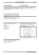
Voltage Range Selection
Set the Timer/Counter to the local line voltage before con-
necting it. As delivered the Timer/Counter may be set to
either 115 V or 230 V. The setting is indicated on the volt-
age range selector on the rear panel.
If the voltage range setting is incorrect, set the selector in
accordance with the local voltage before connecting the
power cable to the line.
PM 9604
INCLUDED OPTIONS
PM 9605
PM 9607
PM 9608B
Figure 3
Options Label on Rear
10MHz 0.5-15Vrms
EXT REF INPUT
VOLTAGE
SELECTOR
PM 9604
INCLUDED OPTIONS
PM 9605
PM 9607
PM 9608B
IEEE 488 INTERFACE
TALK ONLY
ADDRESS
16 8 4 2 1
ON
O
F F
SUPPORTED
FUNCTIONS:
SH1,AH1
T5,L4
SR1,RL1
DC1,DT1
E2
THERMAL FUSE IN
MAINS TRANSFORMER
Figure 4
Location of Voltage Range Selector.
INSTALLATION
Page: 7
PM 6666 - OPERATORS MANUAL


