background image

Troubleshooting


50 

Rev. A1  Mar 2015 


ScanIR3


9


Troubleshooting 

Checkpoint 

Possible Cause / Solution 

Scanner 


Check the wiring of the whole system (correctly fitted connectors, cable damage). 


Check the power for the scanner on scanner’s backside LED: green L

ED

 is “on” 


Check the rotation of the internal scanner mirror assuming the power is on (viewing or hearing 

test). 


The main power for processor box and PC should be provided at the same location. 


Avoiding scanner overheating. Maximum internal housing temperature: 60°C (140°F). The 

internal housing temperature is displayed in the status bar of the scanner software. 


In case of the scanner’s cooling, check for condensation in the scanner’s housing 


condensation can cause the total outage of the unit. To avoid condensation see section 5.6.1 

Avoiding Condensation

, page 31. 


Mount the scanner and the cables away from motors or heaters that produce strong electrical 

fields. 


A dirty measurement window or an obstructed field of view could cause erroneous temperature 

values 

Ethernet 

Communication


Make sure that the scanner’s Ethernet settings are setup correctly, see section 5.4.1 

Ethernet 

Settings

, page 27. 


Make sure that the PC network adapter is setup correctly, see section 5.4.2 

Changing the 

Ethernet Settings for the PC

page 28. 


<Start> <Settings> <Network Connections> provides a list of all available network connections. 

The desired network connection needs to be related to your real adapter device (and no wireless 

or virtual adapter). The status for the connection needs to be <Connected>. 


Disable the PC network adapter temporarily: 

<Start> <Settings> <Control panel> <System> <Hardware> <Device Manager> <Network 

adapters> 

Summary of Contents for IRCON ScanIR3

Page 1: ...ScanIR3 Linescanner Operating Instructions Rev A1 Mar 2015 60901...

Page 2: ......

Page 3: ...an Headquarters Berlin Germany Tel 49 30 4 78 00 80 info ircon eu Fluke Service Center Beijing China Tel 86 10 6438 691 Tel 86 10 4008103435 Service info ircon com cn Internet http www ircon com Lines...

Page 4: ...tware described herein will function properly in every hardware and software environment This software may not work in combination with modified or emulated versions of Windows operating environments...

Page 5: ...ronment 19 5 1 3 Electrical Interference 19 5 1 4 Geometry 19 5 2 MOUNTING 20 5 3 WIRING 21 5 3 1 Overview 21 5 3 2 Cable Entry System 23 5 3 3 Scanner Head Cable 24 5 3 4 Input Output Modules 25 5 3...

Page 6: ...WS 40 7 5 REPLACEMENT KIT FOR SCANIR2 COOLING HOUSING 41 7 6 FIBER OPTIC RJ45 ETHERNET CONVERTER 45 8 MAINTENANCE 46 8 1 REMOVING THE ADAPTER HOUSING 47 8 2 CLEANING THE WINDOW 48 8 3 REPLACING THE WI...

Page 7: ...y regulations Acceptable Operation This instrument is intended only for temperature measurement and is appropriate for continuous use The instrument operates reliably in demanding conditions such as i...

Page 8: ...g the optimal use of the instrument Earth ground Protective ground Fuse Normally open NO relay Normally closed NC relay Switch or relay contact DC power supply CAT I Measurement Category I Conforms to...

Page 9: ...ctly Make sure the ground conductor in the mains power cord is connected to a protective earth ground Disruption of the protective earth could put voltage on the chassis that could cause death Replace...

Page 10: ...sponse S330 3 to 5 m S339 3 9 m S335 3 5 to 4 m S350 5 m S34x 3 43 m S320 1 6 m S310 1 m Detectors S330 S339 S335 S350 S34x MCT S320 InGaAs S310 Si System Accuracy1 S330 2 C 4 F S339 0 5 of reading or...

Page 11: ...tance All models 1 52 m 69 in standard focus special focal distances available minimal focal distance 500 mm 20 in S335 far focus Optical Resolution D S 2 Measurement Resolution 90 energy S330 S339 S3...

Page 12: ...Technical Data 12 Rev A1 Mar 2015 ScanIR3 Figure 1 Optical Resolution for Measurement Resolution depending on Scan Rate Figure 2 Optical Resolution for Hot Spot Detection depending on Scan Rate...

Page 13: ...Technical Data ScanIR3 Rev A1 Mar 2015 13 2 2 1 Optical Diagrams The focus distance is measured from the front end of the scanner Figure 3 Diagrams for selected Optical Resolutions 90 energy...

Page 14: ...the mechanical scanning system at 48 Hz scan rate Environment Rating IP65 NEMA 4 in accordance to IEC 60529 Ambient Temperatures1 All models 0 to 50 C 32 to 122 F without cooling max 180 C 356 F with...

Page 15: ...ter diameter 11 3 mm 0 44 in Minimal bending radius 135 mm 5 3 in moved 85 mm 3 3 in non moved Processor Box Temperature Range 0 to 50 C 32 to 122 F 30 C 22 F with internal heater Material sheet steel...

Page 16: ...canner with head cable Processor box with internal power supply Operating Instructions also included as PDF file on the CD ROM Software CD with ScanView Pro Protocol Manual only as PDF file on the CD...

Page 17: ...ity of the emitted infrared radiation is thereby used to determine the temperature of the target Since the intensity of the infrared radiation is dependent on the material the appropriate emissivity c...

Page 18: ...5 of its revolution the linescanner scans the field of view FOV This corresponds to a scan angle of 90 The remaining 75 of its revolution is used for the internal operation of the sensor The rotating...

Page 19: ...ng must be between 0 C to 60 C 32 F to 140 F during operation and never more then 65 C 150 F at any time including non operation 5 1 2 Environment The linescanner complies with class IP65 and is there...

Page 20: ...stance to target The relationship between the scan line width L and the distance D to the front side of the linescanner housing is defined as described above For long distances the scan line width is...

Page 21: ...section 6 2 Sectors page 35 The processor box can be mounted 10 m 33 ft away from the scanner with the standard scanner cable length longer cables are available on request The scanner cable between t...

Page 22: ...Installation 22 Rev A1 Mar 2015 ScanIR3 Figure 9 Terminal Line Scanner Head Cable Modules AC Mains 100 240 VAC 50 60 Hz X4 X3 X2 X1...

Page 23: ...ing1 Lay cable into appropriate grommet and provide strain relief where necessary using cable ties Use appropriate tool to punch through cover on base frame Set catch hooks into the sides of the cut o...

Page 24: ...24 VDC for service only for service only for service only for service only for service only for service only for service only for service only internal relay internal relay trigger input trigger inpu...

Page 25: ...DO gnd DO gnd DO gnd DO gnd DO gnd 6 Output Modules analog 2 channels each 6 Output Modules Relay 2 channels each 1 Output Module digital 16 channels Figure 12 Exemplary Wiring the Output Modules 5 3...

Page 26: ...wire should be slightly longer than the two other wires so if the cable is accidentally pulled the line and neutral wires are disconnected first You need to connect the AC mains Use only cable with 3...

Page 27: ...dress Ask your IT administrator for a free IP address to be used Advanced Ethernet Settings Subnet Mask The Subnet Mask defines the interpretation of the IP address The factory default setting is 255...

Page 28: ...e subnet address is 193 221 142 the host address is 103 The scanner s subnet address must be 193 221 142 as well The host address of the scanner must be in the range from 1 to 254 with the exception o...

Page 29: ...k on Properties 4 Activate the radio button Use the following IP address and make the following settings IP address 192 168 42 x where x is an address between 0 and 255 except 30 which is already used...

Page 30: ...Switch on the scanner Open the Command Prompt window and start a Telnet session by using the command telnet IPAddressScanner Port Windows 7 does not have Telnet enabled by default Enable the Telnet C...

Page 31: ...180 C 356 F 2 l min 0 52 gallons min 15 C 59 F 27 C 80 6 F Tab 1 Efficiency of the water cooling system 5 6 1 Avoiding Condensation If environmental conditions make water cooling necessary it is stron...

Page 32: ...77 30 86 30 86 30 86 35 95 35 95 35 95 35 95 40 104 45 113 0 32 10 50 15 59 15 59 20 68 25 77 25 77 25 77 30 86 30 86 35 95 35 95 35 95 35 95 40 104 40 104 40 104 40 104 45 113 50 122 5 41 10 50 15 5...

Page 33: ...ts Do not use cooled air This could lead to condensation on the linescanners window 5 8 Laser The built in laser sighting function allows fast and precise aiming at small or rapidly moving targets or...

Page 34: ...l scan rate 150 Hz Each revolution 6 6 ms Target viewed for 1 6 ms Internal calculations occur for 5 ms Example Snapshot Mode Target speed 2 meters sec 78 7 in Distance between measured lines is given...

Page 35: ...ven threshold The output range can be configured for either 0 20 mA 4 20 mA or custom configured by user settings The sector size and the emissivity value can be set for each sector even if the sector...

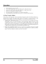
Page 36: ...r can be achieved through one of two methods selected by the user Snapshot mode discontinuous mode The lines are scanned at the set sampling rate and are subsequently stored in the internal memory of...

Page 37: ...t may be ordered at any time and added on site These include the following Mechanical Adjustable Mounting Base S3X RMB Tube Fittings ISO S3X FSISO or NPT S3X FSNPT Spare Windows S3X SWKxxx Replacement...

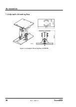
Page 38: ...Accessories 38 Rev A1 Mar 2015 ScanIR3 7 2 Adjustable Mounting Base Figure 16 Adjustable Mounting Base S3X RMB...

Page 39: ...the tubing rests firmly on the shoulder of the tube fitting body and that the nut is finger tight Scribe the nut at the 6 o clock position While holding the fitting body steady with a back up wrench t...

Page 40: ...page 48 Spare Window Spectral Model S3X SWK30 S330 S3X SWK39 S339 S3X SWK50 S350 S3X SWK10 S310 S3X SWK20 S320 S3X SWK43 S34x Tab 3 Available Spare Windows depending on the Spectral Model Each spare w...

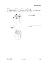
Page 41: ...sing The S3X REPKIT replacement kit is used to install a ScanIR3 Scanner in a legacy ScanIR2 Cooling Housing To mount the scanner into the housing follow the steps given below Mount the fittings on th...

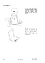
Page 42: ...holes can almost be chosen freely Keep in mind to prevent collisions with other parts of the enclosure Depending on the used tool for mounting the shot fittings the refractory needs holes in a partic...

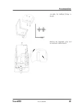
Page 43: ...Accessories ScanIR3 Rev A1 Mar 2015 43 Assemble the bulkhead fittings in the lid Retrieve the alignment poles and mount them in the enclosure...

Page 44: ...der to integrate the internal cooling system of the scanner to the cooling system of the housing the connection between both cooling plates has to be opened Attach two hoses not part of the delivery t...

Page 45: ...d in length without using a repeater A second Fiber Optic RJ45 Ethernet Converter is required to reconvert the fiber optic signals back to TCP IP Ethernet again Ethernet Communications Ports 1x Port c...

Page 46: ...r and solutions to specific problems our customer service representatives are always at your disposal In many cases problems can be solved over the telephone If you need to return equipment to us plea...

Page 47: ...ng the Adapter Housing Remove the four M4x8 screws like shown in the figure Figure 17 Removing the Adapter Housing Turn the scanner up side down and detach the four M6x10 screws Figure 18 Removing the...

Page 48: ...Replacing the Window 1 Remove the surrounding enclosure see section 8 1 Removing the Adapter Housing page 47 2 Remove the 4 hex screws on the back side using a 2 5 mm allen wrench Slide the collar fo...

Page 49: ...g by alternating between the four screws Do not over tighten 8 Install the air purge collar on the housing For correct temperature readings the transmission factor for the new window must be set via t...

Page 50: ...age of the unit To avoid condensation see section 5 6 1 Avoiding Condensation page 31 Mount the scanner and the cables away from motors or heaters that produce strong electrical fields A dirty measure...

Page 51: ...all Windows computers by default PC On some computers the performance of the software can be increased dramatically by switching off the hardware graphic acceleration Start Settings Control Panel Disp...

Page 52: ...ticker should be large enough to cover the target spot Next measure the sticker s temperature using an emissivity setting of 0 95 Finally measure the temperature of an adjacent area on the object and...

Page 53: ...5 0 03 0 03 0 03 Roughened 0 05 0 2 0 05 0 2 0 05 0 15 0 05 0 15 Oxidized 0 2 0 8 0 2 0 9 0 5 0 8 0 5 0 8 Gold 0 3 0 01 0 1 0 01 0 1 0 01 0 1 Haynes Alloy 0 5 0 9 0 6 0 9 0 3 0 8 0 3 0 8 Inconel Oxidi...

Page 54: ...7 0 3 0 6 0 3 0 6 Electrolytic 0 2 0 4 0 1 0 3 0 1 0 15 0 1 0 15 Platinum Black 0 95 0 9 0 9 Silver 0 04 0 02 0 02 0 02 Steel Cold Rolled 0 8 0 9 0 8 0 9 0 8 0 9 0 8 0 9 Ground Sheet 0 5 0 7 0 5 0 7...

Page 55: ...5 Wood Natural 0 9 0 95 Tab 6 Typical Emissivity Values To optimize surface temperature measurements consider the following guidelines Determine the object emissivity using the instrument which is als...

Reviews: