Installation
ScanIR3
25
5.3.4
Input/Output Modules
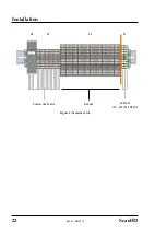
The processor box contains a terminal line which is labeled like shown below. It shows the maximal
stage of expansion for the output modules from the wiring point of view.
Due to limited space, the maximal number of modules is restricted to 11!
X2
X2
X2
21 22 23 24 25 26 27 28 29 30 31 32 33 34 35 36 37 38 39 40 41 42 43 44 45 46 47 48 49 50 51 52 53 54 55 56 57 58 59 60
m
A ou
t1
m
A ou
t2
m
A ou
t3
m
A ou
t4
m
A ou
t5
m
A ou
t6
m
A ou
t7
m
A ou
t8
m
A ou
t9
m
A ou
t10
m
A ou
t11
m
A ou
t12
re
lay
1
re
lay
2
re
lay
3
re
lay
4
re
lay
5
re
lay
6
re
lay
7
re
lay
8
re
lay
9
rel
ay
10
rel
ay
11
rel
ay
12
DO 1
DO 2
DO 3
DO 4
DO 5
DO 6
DO 7
DO 8
DO 9
DO
10
DO
11
DO
12
DO
13
DO
14
DO
15
DO
16
m
A gnd
m
A gnd
m
A gnd
m
A gnd
m
A gnd
m
A gnd
m
A gnd
m
A gnd
m
A gnd
m
A gnd
m
A gnd
m
A gnd
re
lay
1
re
lay
2
re
lay
3
re
lay
4
re
lay
5
re
lay
6
re
lay
7
re
lay
8
re
lay
9
rel
ay
10
rel
ay
10
rel
ay
12
DO
gnd
DO
gnd
DO
gnd
DO
gnd
DO
gnd
DO
gnd
DO
gnd
DO
gnd
DO
gnd
DO
gnd
DO
gnd
DO
gnd
DO
gnd
DO
gnd
DO
gnd
DO
gnd
6 Output Modules, analog
2 channels each
6 Output Modules, Relay
2 channels each
1 Output Module, digital
16 channels
Figure 12: Exemplary Wiring the Output Modules
5.3.5
AC Mains
The processor box does not include a power switch. You must supply a mains disconnect switch. This
switch should be in close proximity to the operator and clearly marked as the power shutoff for the
equipment.
If you use a line conditioner or isolation transformer, connect per manufacturer’s instructions.
Observe grounding instructions and make sure earth ground is supplied to the terminal block of the
processor box.
•
A ground wire must be connected to the (protective earth) terminal.
•
To prevent possible electrical shock, fire or personal injury make sure that the
processor box is grounded before use.
•
Follow all local electrical codes related to installation and grounding of electrical
equipment.
To prevent personal injury, make sure the mains disconnect switch is off before
opening the box lid.
The protective earth screw (marked with and to be found on the bottom side of the
processor box) requires the connection to the local ground by using a 16 mm² (AWG 6)
green/yellow wire.

