


Endurance® Series
Users Manual
22
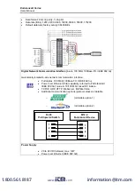
Figure 11: M16 12-Conductor shielded cable with colored wire/signal assignments
If you cut the cable to shorten it, notice that both sets of twisted-pair wires
have drain wires inside their insulation. These drain wires (and the white wire
that is not part of the twisted pair) must be connected to the terminal labeled
CLEAR or SHIELD.
•
Longer cables are available from the factory.
•
Limit power cables to 60 m (200 ft) or less. RS485 cables can be
extended up to 1200 m (4000 ft).
•
Avoid installing the sensor cable in noisy electrical environments
such as around electrical motors, switch gear, or induction heaters.
5.3.3.2. M12 4-Conductor shielded cable
The 4-conductor shielded connecting cable is used to link the Endurance-Series device to a
LAN/Ethernet device. A standardized cable, equipped with a M12 4-pin connector type, D-
coded, suited for industrial Ethernet with IP67 protection rate and a screw retention feature on
one side and a RJ45 connector type on the counter side is used. Via the 4-conductor cable the
Endurance-Series device can also be powered as a PD (Powered Device) by a PSE (Power
Sourcing Equipment) in a PoE (Power over Ethernet) mode. Refer to PoE standard IEEE
802.3af, mode A, 10/100 Mbit mixed DC & data.
Figure 12: M12 4-Conductor shielded cable with RJ45 on counter side
5.3.3.3. Endurance specific terminal block
An Endurance specific terminal block is available to attach the 12-wire color-coded sensor cable
via the terminal block to the process world.
www.
.com
1.800.561.8187


