


Endurance® Series
Users Manual
16
4.3. Electrical Interference
To minimiz
e electrical or electromagnetic interference or “noise” be aware of the following:
Mount the Endurance integrated head device as far away as possible from potential sources of
electrical interference, such as motorized equipment producing large step load changes.
•
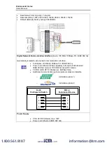
Use shielded wire for all input and output connections.
•
Make sure the shield wire from the electronics to terminal block cable is earth grounded.
•
For additional protection, use conduit for the external connections. Solid conduit is
better than flexible conduit in high noise environments.
•
Do not run AC power for other equipment in the same conduit.
When installing the Endurance sensor head, check for any high-intensity
discharge lamps or heaters that may be in the field of view (either
background or reflected on a shiny target)! Reflected heat sources can
cause a sensor to give erroneous readings.
4.4. Distance to Object
The optimal distance to the measuring object depends on the optical lens focus (F0, F1, F2) of
the sensor head and the needed measurement spot size. Please see section 3.4, Optical
Specifications for detailed information regarding the focus options. The Endurance sensor
placement may vary to suit specific applications. The following sections demonstrate the sensor
placement under various conditions, where 1- or 2-Color temperature measurements deliver
reasonable readings.
4.5. Sensor Placement (
1-Color
Mode)
Sensor placement for 1-Color temperature measurements is more critical than for 2-Color
measurements. The sensor must have an unobstructed view to the target. Any obstruction on
the lens, the front window, or in the atmosphere influences the temperature reading accuracy.
The sensor distance to the target can be anywhere beyond the minimum requirements, as long
as the target completely fills the field of view.
Figure 4: Proper Sensor Placement in 1-Color Mode
Target greater than spot
size
Target equal to spot
size
best
critical
incorrect
Target smaller than spot
size
www.
.com
1.800.561.8187


