Fluke 85RF II Instruction Sheet Download Page 5

 English  

Page 


1

2

5

4

3

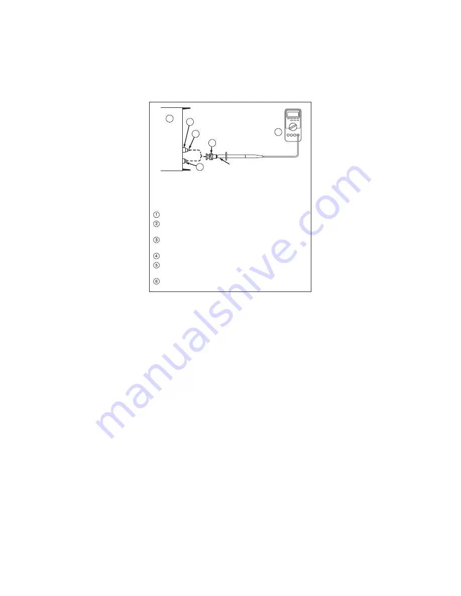
Fluke 85RF Probe under test

6


Required Equipment List 

The following equipment (or equivalent) is required for 
testing the performance of the 85RF II: 


Equipment Type 

Recommended Model

AC Calibrator 

Fluke 5520A-SC600 

50-Ohm Feed Thru 
Termination 


JFW Industries P/N 50L-001

BNC Jack to Banana 
Plug Adapter 


Pomona P/N 1269

BNC to Probe Adapter 

Fluke P/N 574756 

Digital Multimeter, 
3-1/2 Digit (DMM) 


Fluke 87V 

BNC Jack to Jack 
Adapter 


Pomona 3283 


gsk002.eps 

Figure 2. 

Equipment Configuration for Performance Test 

2. The DMM will read between 0.950 V dc and 1.050 V dc. If 

the Probe is functional but is not in these limits, 
disassemble the Probe (refer to the “Probe Disassembly” 
Section in this Instruction Sheet) and adjust R2 for a DMM 
measurement


between 0.990 V dc and 1.010 V dc. 

Reassemble the Probe. 

3. Move the unit in test to the Normal output of the calibrator 

and decrease the output level to 0.250 V rms and 1 MHz. 
The DMM will read between 0.223 V dc and 0.280 V dc. 

4. Set the AC Calibrator to 

STDBY

, decrease the frequency 

to 100 kHz and increase the voltage to 30 V ac rms. (Do 
not increase the voltage to more than 30 V ac.)   

5. Set the AC Calibrator switch to 

OPER

. The DMM will read 

between 28.3 V dc and 31.8 V dc. 

6. Move the unit in test back to the scope output and set the 

level sine to 1 V rms 160 MHz. The DMM will read 
between 0.9 V dc and 1.12 V dc. Increase the frequency 
to 450 MHz. The DMM will read between 0.562 V dc and 
1.780 V dc. 

Summary of Contents for 85RF II

Page 1: ... Product Look for cracks or missing plastic Carefully look at the insulation around the terminals Limit operation to the specified measurement category voltage or amperage ratings Do not touch voltages 30 V ac rms 42 V ac peak or 60 V dc Do not use the Product around explosive gas vapor or in damp or wet environments Do not use and disable the Product if it is damaged Use the Product only as speci...

Page 2: ...ue of an input and is calibrated to read rms value of a sine wave Voltage range 0 25 V rms to 30V rms Maximum input voltage 30 V rms 200 V dc Input capacitance Approximately 9 pF Temperature range Operating 10 C to 35 C Storage 40 C to 75 C Humidity 90 R H Output connector Fits standard 0 75 inch dual banana connectors Accessory BNC to Probe Adapter P N 574756 Pollution degree 2 Operating altitude...

Page 3: ...the Probe 2 Touch the Probe tip to the circuit under test Frequencies greater than 100 MHz To measure frequencies greater than 100 MHz 1 Ground the 4 inch clip lead supplied with the Probe 2 Touch the Probe tip to the circuit under test Note Measurements above 100 MHz must be made with minimum cable lengths and a terminated 50 e system One inch or less of non terminated coaxial cable such as a BNC...

Page 4: ...bration The performance and calibration test is a verification test to make sure that the 85 RF II is functional and correctly calibrated Use the procedure as an acceptance test and or calibration procedure the Probe has one adjustment which is R2 The recommended calibration interval is one year Note If the Probe cannot be calibrated to the specifications in this document the Probe could be damage...

Page 5: ...e limits disassemble the Probe refer to the Probe Disassembly Section in this Instruction Sheet and adjust R2 for a DMM measurement between 0 990 V dc and 1 010 V dc Reassemble the Probe 3 Move the unit in test to the Normal output of the calibrator and decrease the output level to 0 250 V rms and 1 MHz The DMM will read between 0 223 V dc and 0 280 V dc 4 Set the AC Calibrator to STDBY decrease t...

Page 6: ...of the printed circuit board up inch and pull it away from the Probe tip 6 To reassemble the Probe do the steps in this procedure backwards start with step five and end with step one Make sure that the gold pin on the front of the printed circuit board aligns correctly in the Probe tip and that the ground lead nut is aligned with the hole in the Probe body How to Clean the Probe WXWarning For safe...

Reviews: