background image

6.7.6. Saving and restoring the unit settings

IMPORTANT

Note that transceiver software configuration (*.CONF) files are
not  interchangeable  with  RACER  configuration  setup
(*.FMCONF) files.

The 

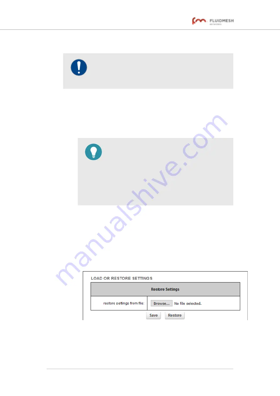
LOAD OR RESTORE SETTINGS

 window contains controls that allow

you to:

• Save  the  unit's  existing  software  configuration  as  a  configuration

(*.CONF) file.

• Upload and apply a saved configuration file to the current unit.

TIP

Saved configuration files can be copied and distributed
for  use  on  more  than  one  Fluidmesh  unit  of  the  same
type,  simplifying  the  configuration  of  other  deployed
units.

Saved  configuration  files  can  also  be  used  for
configuration  backup.  This  can  greatly  speed  up  re-
deployment if a damaged unit must be replaced with a
unit of the same type.

To download the unit's existing configuration settings to your computer, do
the following steps:

1.

Click the 

-configuration settings

 link under 

MANAGEMENT

SETTINGS

 in the left-hand settings menu.

• The 

LOAD OR RESTORE SETTINGS

 dialog will be shown

(

Figure 75 (page 146)

).

Figure 75. Configurator GUI (LOAD OR RESTORE
SETTINGS dialog)

2.

Download the unit's configuration (*.CONF) file to your computer
by clicking the 

Save

 button and following the software prompts.

Fluidmesh 4200 FIBER

© Fluidmesh Networks LLC

Page 146 of 180

Summary of Contents for 4200 FIBER

Page 1: ...Fluidmesh 4200 FIBER Installation and Configuration Manual Edition 1 6 Firmware V8 3...

Page 2: ...h Network Architecture 17 3 2 5 Point To Multipoint Architecture With FluidMAX 18 3 3 Fluidmesh Network Addressing 20 3 3 1 Bridge IP Addressing 20 3 3 2 Unit Identification And Addressing 20 Mesh And...

Page 3: ...he Configurator Interface 50 6 1 Software And Hardware Prerequisites 52 6 2 Accessing The Fluidmesh 4200 FIBER For Device Configuration 52 6 2 1 Local Access And Login For Initial Configuration 53 6 2...

Page 4: ...Devices 107 6 6 6 SNMP Configuration 110 Using SNMP V2c 111 Using SNMP V3 112 6 6 7 Wireless Access Point Configuration 114 6 6 8 RADIUS Configuration 119 6 6 9 NTP Configuration 122 6 6 10 L2TP Conf...

Page 5: ...Requirements 165 10 Heat Radiation Data 167 11 Federal Communications Commission FCC Radio Interference Statement 168 12 Notices And Copyright 171 13 Fluidmesh End User License Agreement 173 13 1 Pre...

Page 6: ...ER interface or the device s local Configurator interface do not make configuration changes unless you know with certainty that your changes will not negatively impact people or animals in the vicinit...

Page 7: ...F radiating devices such as antennas when such devices are powered ON Never stand in line with a powered RF radiating device Before activating any device capable of transmitting RF signals make sure t...

Page 8: ...t from laser or LED sources that may cause temporary or permanent blindness For additional guidance regarding the safe use of laser based and LED based fiber optic technology refer to ANSI Z136 2 Safe...

Page 9: ...ces of transceiver and gateway unit enclosures may become hot during normal operation During normal operation do not touch or handle the unit enclosure without personal protective equipment Fluidmesh...

Page 10: ...an help improve this manual If you find any mistakes or if you know of a way to improve the procedures that are given please let us know by E mailing your suggestions to documentation fluidmesh com Fl...

Page 11: ...s reliable service in high speed applications for example servicing extremely fast moving trains and must be connected to one or more external antennas The unit is designed primarily for mobility appl...

Page 12: ...chosen If a newer network is being built or upgraded the advanced Prodigy 2 0 protocol can be selected to boost performance If an older network incorporating Fluidmesh components is being upgraded the...

Page 13: ...depending on data traffic load signal strength environmental conditions such as line of sight and atmospheric moisture and other factors Note that the power consumption of transceiver units tends to...

Page 14: ...ireless network architectures Depending on the network design and the type of components used the Fluidmesh 4200 FIBER can be used to create wireless network architectures including Point to point P2P...

Page 15: ...only features Prodigy selection if the installed Prodigy engine includes the selection feature Fluidmesh devices that are designed to operate exclusively in Bridge Mode in other words in point to poin...

Page 16: ...Select the Prodigy version you need by using the General Mode page of the Configurator interface RACER RACER is Fluidmesh s web based configuration portal It is the primary interface with which to con...

Page 17: ...re but can also fill more traditional networking roles if needed This allows substantial reliability and flexibility advantages when compared to traditional wireless solutions A simplified example of...

Page 18: ...co ordination protocol for wireless mesh networks The FluidMAX protocol is based on the concept of point to multipoint network architecture Figure 3 page 19 with improved features and capabilities th...

Page 19: ...g a default communication channel width of 40 MHz the MAC protocol used by FluidMAX is capable of supporting data throughput of up to 150 Mb s Provided that the sum of the data throughput requirements...

Page 20: ...and addressing Mesh and bridge capable radio transceiver identification CAUTION This section contains theoretical explanations of the underlying concepts behind mesh network addressing and is intende...

Page 21: ...emonstrating the relationship between a wired LAN and a linked mesh radio network containing a mesh end unit and mesh point units is shown in Figure 5 page 21 Figure 5 Fluidmesh Network Addressing Ope...

Page 22: ...address but with a unique unit identification number When a Fluidmesh wireless network is connected to a wired LAN the LAN is usually the private control room LAN Therefore Fluidmesh radio transceiver...

Page 23: ...ed IP address If dynamic IP addressing is used the components may not be accessible to third party software that relies on the components for data input A typical example is a video surveillance syste...

Page 24: ...for details As a Master radio unit or Slave radio unit within a point to multipoint wireless network see Using the FluidMAX Management Setting in Advanced radio settings page 97 for details Installati...

Page 25: ...NGTH LEDs light up in sequence During the boot sequence the LEDs indicate the following conditions 1 Red Core system boot in progress 2 Yellow Wireless system boot in progress 3 First green Routing en...

Page 26: ...802 3af or IEEE 802 3at A 48 Vdc power source equipped with an M12A connector When providing the power source for the Fluidmesh 4200 FIBER remember the following important points Install the power sou...

Page 27: ...e fiber optic transceiver 4 1 4 Rebooting the firmware and resetting the unit to factory defaults The Fluidmesh 4200 FIBER hardware can be rebooted and reset to factory default condition using the pro...

Page 28: ...ACER refer to the Fluidmesh Networks RACER User Manual 3 To do the reset by physically accessing the unit follow the procedure below To reset the radio to its factory default settings do the steps tha...

Page 29: ...lly examined to verify that no corrosion or water ingress were found Verification of resistance to fluctuating temperatures This consisted of placing the unit in a climatic chamber and subjecting it t...

Page 30: ...iver does not make use of a dual redundant power supply Therefore terminals 2 and 4 are not used M12 A coded eight pin pre September 2016 only Female M12 A coded eight pin connectors below are used on...

Page 31: ...ith white tracer to terminal 3 of RJ45 Terminal 6 of M12A Orange wire with white tracer to terminal 1 of RJ45 Terminal 7 of M12A Blue wire to terminal 4 of RJ45 Terminal 8 of M12A Green wire to termin...

Page 32: ...ded connector to one end of an Ethernet cable and a male RJ45 Ethernet connector to the other end of the Ethernet cable the terminal assignments are as follows Terminal 1 of M12X Orange wire with whit...

Page 33: ...e Use of Optical Fiber Communication Systems Utilizing Laser Diode and LED Sources IMPORTANT Fiber optic compatible Fluidmesh gateways and transceivers are shipped from the factory without fiber optic...

Page 34: ...components within a minimal period of time 2 Remove the protective cap covering the connection ports of the SFP module 3 Slide the round threaded tube that covers the SFP port connector back along the...

Page 35: ...unit NOTE If the unit must be powered using an IEEE 802 3at compliant network switch or PoE injector disregard this section and proceed to Connecting LAN cables to the unit page 36 When the Fluidmesh...

Page 36: ...of the male connector onto the female connector Tighten the connection by hand 4 2 3 Connecting LAN cables to the unit M12X LAN cable IMPORTANT If a local area network LAN connection must be made to...

Page 37: ...accepted standard for M12X LAN PoE connectors Next proceed to the steps in the following table 3 Remove the protective plastic plug from the port labelled LAN 4 Wrap PTFE thread sealing tape around t...

Page 38: ...ts or accessories please contact your local Fluidmesh Networks representative for assistance Due to the large variety of XCO type fiber optic transceivers that are available Fluidmesh Networks ships t...

Page 39: ...ab type module has a tab that is pulled to remove the module below The actuator button type module has a button that is pushed to remove the module below Fluidmesh 4200 FIBER Fluidmesh Networks LLC Pa...

Page 40: ...To install an XCO type SFP module in the Fluidmesh 4200 FIBER do the following steps 1 Wear an ESD preventive wrist or ankle strap and follow its instructions for use 2 Make sure that the SFP module...

Page 41: ...e fiber optic cable from the SFP module before removing or installing the module 3 Insert a clean dust cover into the SFP module s interface port 4 Remove the SFP module from its receptacle using the...

Page 42: ...If the SFP module is a bale clasp type close the bale clasp before inserting the cable connector into the module 3 Insert the cable connector into the SFP module s interface port 4 If applicable press...

Page 43: ...adiall CAUTION Do not remove the protective rubber sleeves from a female QMA plug below if an antenna will not be connected to the plug Unprotected QMA plug contacts that are exposed to water will oxi...

Page 44: ...d antenna cable above 5 Push the male QMA plug of the antenna cable into the female QMA plug of the unit 6 Screw the threaded sleeve of the male plug onto the female plug Tighten the connection by han...

Page 45: ...ion on which browsers are supported refer to Table 3 page 45 below If needed upgrade your browser version 2 Click this link The Fluidmesh Partner Portal Sign In dialog will be shown 3 Register as a po...

Page 46: ...me password OTP for each login To set up two factor authentication do the following steps 1 Install an app capable of generating authentication codes on your mobile phone Apps recommended for specific...

Page 47: ...code field of the Two Factor Authentication web page The Two Factor Authentication web page will show a QR code 7 Use the authentication app on your mobile phone to scan the QR code on the web page Fi...

Page 48: ...ou can operate RACER using any internet connected computer with a web browser To access the RACER portal do the following steps 1 Log in to the Fluidmesh Partners Portal using your login credentials 2...

Page 49: ...idmesh Partners Portal using your login credentials 2 Click this link 3 All documents are arranged by category Browse the folders for the documentation you need Fluidmesh 4200 FIBER Fluidmesh Networks...

Page 50: ...an Offline basis in other words if the device is not connected to the internet and therefore cannot access its configuration settings from the RACER Cloud Server a separate configuration file can be u...

Page 51: ...wardscompatibility with Fluidmesh units that are no longer in production Noise floor Calibration Shows the unit s current noise floorcalibration setting MAX Transmission MCS Used to choose the modulat...

Page 52: ...a detailed description of the configuration options featured in the RACER interface refer to the Available configuration parameters section of the Fluidmesh Networks RACER User Manual 6 1 Software and...

Page 53: ...ot sequence to complete 3 Connect one end of a CAT5 6 Ethernet cable to the computer that will be used to configure the Fluidmesh 4200 FIBER 4 Connect the other end of the Ethernet cable to an unused...

Page 54: ...theft Because the Fluidmesh 4200 FIBER is connected to the computer using an unsecured connection in this case a CAT5 6 cable the web browser may show you security warnings like the one above This is...

Page 55: ...re as follows Username admin Password admin 9 Enter the correct username and password Press Enter If your browser shows a time out or similar message the computer may be trying to access the Fluidmesh...

Page 56: ...6 2 2 Initial configuration with the unit in Provisioning Mode The Fluidmesh 4200 FIBER cannot be operated without entering some basic configuration settings These settings allow the unit to connect t...

Page 57: ...it is in Provisioning Mode by looking at the colored icon to the right of the RACER tag in the upper left hand corner of the screen Figure 16 page 57 Figure 16 RACER status icon Provisioning Mode If t...

Page 58: ...ght green green orange red then from right to left red orange green green The LEDs will repeat this cycle until the unit either enters a Fallback condition or enters Online or Offline mode The unit wi...

Page 59: ...ut cannot connect to the Partners Portal the unit s IP address will automatically be set to 192 168 0 10 24 If the unit cannot connect to the Partners Portal verify that the Partners Portal can be rea...

Page 60: ...on to go back to the RACER dialog and adjust the settings If you click the OK button the unit will reboot but will remain in Provisioning Mode The unit will attempt to connect to the internet using th...

Page 61: ...tial configuration process refer to the flowchart below NOTE Each individual Fluidmesh radio transceiver unit has a factory set mesh identification number that takes the form 5 w x y If the unit s IP...

Page 62: ...og in To switch between Offline and Online modes do the steps that follow 1 Log in to the Configurator interface as shown in Accessing the Fluidmesh 4200 FIBER for device configuration page 52 The Con...

Page 63: ...king if you want to switch the unit to the chosen mode 4 To switch the radio to the chosen mode click the Confirm button A ten second countdown will be shown The Configurator interface web page will r...

Page 64: ...ce refer to the Fluidmesh Networks RACER User Manual A configuration file that has been created using the RACER interface must be uploaded to the unit To upload a RACER configuration file do the follo...

Page 65: ...e unit s LAN parameters If the local unit is in Bridge Mode the Bridge ID of the remote unit to which the local unit must be linked To change the General Mode settings do the following steps Click the...

Page 66: ...y of two wireless units If needed change the unit s operational mode by clicking one of the following Mode radio buttons bridge This mode creates a layer 2 connection between the local unit and anothe...

Page 67: ...connection with the closest available Fluidmesh unit that is set to Bridge Mode Alternatively choose the correct unit from the list of available units 3 Save the operational mode settings by clicking...

Page 68: ...gher 2 Configuring all network components within the same network to operate using either Prodigy 1 0 or Prodigy 2 0 Option 2 is recommended if the network does not contain older Fluidmesh devices tha...

Page 69: ...settings Modifying the wireless settings IMPORTANT If the Fluidmesh 4200 FIBER was purchased in the USA or Canada the Country selection is set to the country of purchase and the Country drop down wil...

Page 70: ...y drop down menu CAUTION Different countries frequently have differing telecommunications regulations If the Country listing is not set correctly the unit may violate national telecommunications legis...

Page 71: ...ons contain important technical and regulatory information that influences the settings on the WIRELESS RADIO window For information on the effects of network topology on frequency selection refer to...

Page 72: ...and an ideal distance of 5ft 1 5m between them Mounting radio transceiver units back to back or side by side may cause co location interference that will degrade performance across your network Channe...

Page 73: ...IMPORTANT The dynamic frequency selection feature must be enabled using a software plug in Fluidmesh part number FM UNII2 Contact your Fluidmesh Networks representative for details If it is essential...

Page 74: ...alled The Partner Portal will verify that there are no TDWR radar installations within 40 miles 64 Km of the Fluidmesh unit If no TDWR radar installations are found the plug in will grant permission f...

Page 75: ...AND STATS window will be shown Figure 27 page 75 Figure 27 Configurator GUI Antenna alignment and stats dialog 2 More than one two way wireless link may be shown in the Detected Links table Find the t...

Page 76: ...ical antenna alignment by manually adjusting the location and direction of the relevant antenna During the alignment use the graph and bar readings to monitor variations in signal strength 6 To increa...

Page 77: ...ll be empty 2 Choose a range for the frequency band that must be scanned for interference or excessive radio noise by doing either of the following Set the start and stop frequency selection to the sy...

Page 78: ...nformation for an access point hover the mouse cursor over the access point icon The SSID number MAC address and signal strength will be shown for the chosen AP To see detailed information for the sig...

Page 79: ...or GUI Ping Softdog dialog 2 To set up a constant ping to one or more IP addresses do the following steps 1 Enter the IP address in the field to the left of the Add IP button 2 Click the Add IP button...

Page 80: ...twork against the background of an aerial map CAUTION Do not change the settings in the VLAN Manager table Changing these settings may have a negative impact on VLAN configuration Plotting and interpr...

Page 81: ...inks are shown as lines Primary wireless links are shown as double pointed solid red lines If the network includes mesh radio links these are shown as double pointed dashed lines Wired LAN links are s...

Page 82: ...ized particularly if the Fluid Throttle plug in is installed If a Fluidmesh device is not performing as expected the dot representing the unit turns yellow If the dot is clicked the warning details wi...

Page 83: ...n changed and the Save Layout button has not been clicked you can restore the visual network layout to its last saved configuration by clicking the Load Layout button Using and interpreting the wirele...

Page 84: ...due to transmission errors Signal Strength The current signal level being received in dBm Link Utilization In pie chart format The percentage of current link utilization for data transmission 4 To vi...

Page 85: ...re recorded for the previous two days at a sampling interval of five minutes The statistical recording time can be set at a maximum of 24 days Note that if the statistical recording time is increased...

Page 86: ...ure 31 page 81 all visual warnings for all devices and wireless links that are not currently performing as expected will be shown Visual warnings that may be shown for radio units are as follows Ether...

Page 87: ...unit by clicking the Name field for the unit and entering the text of the name 3 Collapse the table by clicking the button again Adding an aerial map to the FMQuadro view You can add an aerial image...

Page 88: ...lobytes TIP Suitable aerial images can be created and downloaded using Google Earth Basic instructions on how to use Google Earth are available here Images must be uploaded to FMQuadro using Google Ch...

Page 89: ...h For detailed information on the operational concepts behind Fluidity and instructions on how to configure the protocol refer to the Fluidmesh Networks Fluidity Configuration Manual IMPORTANT Softwar...

Page 90: ...you will be prompted to download and install the plug in A graphical view of the current network will be shown A typical example is shown in Figure 38 page 90 Figure 38 Fluidity Quadro graphical view...

Page 91: ...segments around the dot representing the static device A typical example of a link between a static device and multiple mobile devices is shown in Figure 40 page 91 Figure 40 Fluidity Quadro multiple...

Page 92: ...t click and drag the dot to the needed position 5 To save the network layout currently seen on the map view click the Save Layout button 6 If the positions of any device dots have been changed and the...

Page 93: ...listed in the table 1 Each mobile unit is represented by a chosen color on the Fluidity Quadro display For example the first unit in the table 5 0 4 136 has been assigned a medium blue color On the g...

Page 94: ...12 101 2 is represented on each graph as a purple line Choose a unique color to represent each static Fluidmesh device by clicking the colored tile to the right of the device name and clicking the cho...

Page 95: ...dvanced Tools dialog click the advanced tools link under NETWORK CONTROL in the left hand settings menu Using the Ping test tool The Ping test can be run while the network is under load to test operat...

Page 96: ...rate computation is CPU intensive and must be regarded as indicative only Note that bandwidth testing tends to underestimate the actual link throughput To use the Bandwidth test tool do the following...

Page 97: ...tested between the Fluidmesh unit and another unit in the wireless network Get the IP address of the other unit 2 Enter the IP address of the second unit in the Path MTU discovery field Figure 46 page...

Page 98: ...Radio Settings dialog click the advanced radio settings link under ADVANCED SETTINGS in the left hand settings menu below Figure 47 Configurator Advanced Radio Settings Using the FluidMAX Management S...

Page 99: ...e unit will scan the spectrum of available frequencies for a Master unit that shares its Cluster ID and its frequency selection feature will be disabled OFF The FluidMAX engine will be disabled 3 If t...

Page 100: ...option the unit will automatically choose the most efficient transmission power level according to prevailing conditions However the unit will not exceed the last manually selected Max TX Power param...

Page 101: ...on will not be available 3 Click the Save button to save your settings Alternatively clear the settings by clicking the Cancel button Using the Maximum link length setting This setting is used to set...

Page 102: ...ocal Fluidmesh Networks representative for assistance The SFP ETHERNET SETTINGS window contains controls to change the data exchange speeds of the unit s duplex fibre optic link and RJ45 Ethernet port...

Page 103: ...rk Reach gateways such as Internet gateways Create networks that include fixed devices such as CCTV cameras To change the Static Routes settings click the static routes link under ADVANCED SETTINGS in...

Page 104: ...t routing IMPORTANT The same Whitelist or Blacklist must be applied to all transceiver units that are part of a defined network Failure to use the same Whitelist or Blacklist may cause units to incorr...

Page 105: ...If a wireless link is not specified in a Whitelist it will be assigned the lowest routing priority but will not be completely excluded from routing 3 Example 1 If you want to create a simple Whitelis...

Page 106: ...the links between unit ID numbers 5 2 22 136 and 5 29 252 213 Figure 52 page 106 Cell A1 of the CSV file would contain the parameter 5 2 22 136 5 29 252 213 Cell A2 of the CSV file would contain the...

Page 107: ...SV file click the Clear Whitelist Blacklist button To delete the Whitelist or Blacklist CSV file click the Reset button 6 6 5 Multicast Multicast management for mesh network capable devices Multicast...

Page 108: ...re that the unit is in Mesh End mode as shown in Changing the operational mode page 66 Multicast controls are not available if the unit is set to Mesh Point mode To set multicast rules on a Mesh End u...

Page 109: ...forwarded Destination address wildcards can also be used For example the destination address 5 255 255 255 represents all Fluidmesh units in the wireless network 5 Enter the multicast group designator...

Page 110: ...e used to configure an SNMP v2c or SNMP v3 service to run on the Fluidmesh 4200 FIBER Both walk throughs no agent to manager notifications and traps agent to manager notifications enabled are supporte...

Page 111: ...om the factory with SNMP disabled Using SNMP v2c To change the unit s SNMP mode to v2c and configure the unit accordingly do the following steps 1 Click the SNMP mode drop down and click the v2c optio...

Page 112: ...You can also configure the unit to send SNMP traps at defined periodic intervals If needed enable periodic SNMP traps by checking the Enable SNMP periodic trap check box and enter the name of the netw...

Page 113: ...rd in the SNMP v3 password field The default password is fluidmesh To show the password as it is being typed check the Show SNMP v3 password check box 4 Choose the correct authentication protocol from...

Page 114: ...re sent must have an SNMP agent configured to collect v2c traps 8 You can also configure the unit to send SNMP traps at defined periodic intervals If needed enable periodic SNMP traps by checking the...

Page 115: ...procedures page 155 IMPORTANT If the FM AP plug in is not installed on the radio unit the Fluidmesh WiFi link will not appear in the left hand settings menu 2 Open the FLUIDMESH 802 11 INTERFACE dial...

Page 116: ...he radio unit is a part are isolated from each other by location on different subnets 4 If the wireless AP has been set to routed configuration and access to other Fluidmesh radio units that are part...

Page 117: ...sen range by entering the address in the DHCP first IP address entry field c Specify the last DHCP IP address in the chosen range by entering the address in the DHCP last IP address entry field IMPORT...

Page 118: ...phrase in plain text as it is being entered check the Show Passphrase check box 7 Click the Network Protocol drop down menu If the wireless station must dynamically assign itself a wireless LAN IP add...

Page 119: ...nd passphrase 2 Use the web browser on your computer or other wireless interface device to access the offline Configurator interface 3 Configure the radio unit as shown in this manual 6 6 8 RADIUS con...

Page 120: ...Disabled RADIUS functionality will be disabled Enabled RADIUS functionality will be enabled and the configuration options will be shown Passthrough If the device is a trackside mounted Fluidity devic...

Page 121: ...Authentication Protocol 9 Enter the personal username for access to the RADIUS server in the Username field 10 Enter the personal password for access to the RADIUS server in the Password field To read...

Page 122: ...er If the unit cannot synchronize with its primary time server and the host name of a backup time server is entered the unit defaults to synchronizing with the backup server CAUTION The same NTP confi...

Page 123: ...s by clicking the Reset button 6 6 10 L2TP configuration IMPORTANT The L2TP configuration option is only available if the Fluidmesh 4200 FIBER is set to Mesh Point mode or Mesh End mode If the unit is...

Page 124: ...to the Fluidmesh Networks L2TPv3 Configuration Manual 6 6 11 VLAN settings VLAN configuration The VLAN SETTINGS window contains controls to connect the Fluidmesh 4200 FIBER to one or more virtual loc...

Page 125: ...wn Figure 63 page 125 Figure 63 Configurator GUI VLAN SETTINGS dialog 2 Connect the unit to a VLAN that is part of the local wireless network by checking the Enable VLANs check box 3 Check the Enable...

Page 126: ...ied VID Tagged packet with valid VID Packet dropped Tagged packet with null 0 VID Packet dropped Access port rules for outgoing packets Case and Action Tagged packet with configured and allowed VID Pa...

Page 127: ...rt rules for outgoing packets with unit in Bridge Mode Case and Action Tagged packet with valid VID from remote peer Packet passed tagged Tagged packet with null 0 VID from remote peer Packet passed u...

Page 128: ...e for the unit by clicking the Unit Role drop down and clicking the correct option from the list below Infrastructure Choose this setting if the unit is connected to a wired LAN and or a network that...

Page 129: ...anually assigned the Vehicle ID string must be unique for every individual Fluidmesh unit operating on the same network even if more than one Fluidmesh unit is installed on the same vehicle 5 The netw...

Page 130: ...communicate directly with an infrastructure point this setting allows data traffic to be routed from the source vehicle through a second vehicle to an infrastructure point IMPORTANT If the Allow V2V...

Page 131: ...used to identify the Fluidmesh 4200 FIBER within the FMQuadro network map and to other Fluidmesh utilities The operation of the physical Reset button on the unit Device firmware upgrades by trivial f...

Page 132: ...ng utilities such as the FMQuadro network map 3 Set the functionality of the unit s hardware Reset button by clicking the Reset Button function drop down and clicking the needed option as described be...

Page 133: ...do the steps that follow a Check the Enable Automatic Upgrade check box b Enter the IP address of the authorized TFTP server containing the firmware update source files in the TFTP Server field c Ent...

Page 134: ...ng privileges for the View Mode settings window requires the correct administrator user name and password To change the administrator user name and password for the current user do the following steps...

Page 135: ...g the Reset button To change the View Mode settings do the following steps 1 Log in to the unit s Configurator GUI with Administrator credentials See Accessing the Fluidmesh 4200 FIBER for device conf...

Page 136: ...ttings by clicking the Save button in the Allow View Mode Settings section Alternatively clear the settings by clicking the Reset button 6 7 2 Changing the Administrator username and password The CHAN...

Page 137: ...tly spelled by checking the Show Password check box to show the text of the password then re entering the password in the Confirm New password field 6 Save the changed password settings by clicking th...

Page 138: ...ange button Alternatively revert to the old password settings by clicking the Reset button 6 7 3 Overwriting and upgrading the unit firmware The FIRMWARE UPGRADE window contains controls to overwrite...

Page 139: ...ables from the Fluidmesh device 3 With the Fluidmesh device disconnected from the wireless network power ON the device CAUTION Do not restart or power OFF the device while firmware overwriting is in p...

Page 140: ...e sure that the upgraded firmware has a greater version number than the firmware that was previously installed If the firmware version has not changed the firmware upgrade has failed Repeat the overwr...

Page 141: ...trial period IMPORTANT The 4 9 GHz band is not available in Brazil or Canada Show and erase the log files for plug in installation To open the MANAGE PLUG INS dialog do the following steps Click the...

Page 142: ...Figure 72 Configurator GUI typical MANAGE PLUG INS dialog Fluidmesh 4200 FIBER Fluidmesh Networks LLC Page 142 of 180...

Page 143: ...gement procedures page 155 To assign a software plug in on the Partner Portal to the unit do the following steps 1 Enter the activation code for the plug in in the Plug in Activation Code field 2 Clic...

Page 144: ...ic Fluidmesh device settings including the unit s MAC address and controls that allow you to download diagnostic data files and view device event logs To use the status window do the following steps C...

Page 145: ...rent device log for the unit click the Show Logs button The current device log will be shown in the Device Logs window above the Show Logs button The status messages shown in the log relate to possibl...

Page 146: ...the configuration of other deployed units Saved configuration files can also be used for configuration backup This can greatly speed up re deployment if a damaged unit must be replaced with a unit of...

Page 147: ...n other words to do a hard reset IMPORTANT Doing a hard reset will revert all unit configuration settings including the unit s IP address and administrator password to factory defaults If you want to...

Page 148: ...the reboot link under MANAGEMENT SETTINGS in the left hand settings menu The unit reboot dialog will be shown Figure 77 page 148 Figure 77 Configurator GUI unit reboot dialog 2 Reboot the unit by clic...

Page 149: ...ser license agreement for the Fluidmesh 4200 FIBER its firmware and control software To view the terms and conditions of the license agreement click the License Agreement link under MANAGEMENT SETTING...

Page 150: ...user license agreement will be shown under a new tab in your web browser To download the end user license agreement as a standard text TXT file do the following steps 1 Right click the Download the L...

Page 151: ...ble and re installable Function Part number Bandwidth Yes A range of plug ins are available to enable increased traffic forwarding bandwidth up to and including the amount of bandwidth specified in th...

Page 152: ...model number FLU TRK bandwidth limit FMx500 models 4 9 GHz band Yes Enables operation in the 4 9 GHz emergency band Note that the 4 9 GHz band is not available in Brazil and Canada FM 49 Licensed Fre...

Page 153: ...The following tables describe which plug ins are compatible with specified Fluidmesh devices Table 7 Device plug in compatibility FM 1000 to FM 1300 OTTO Plugin FM 1000 Gateway FM 10000 Gateway FM PON...

Page 154: ...ble UNII2 Not available Not available Available Not available Table 8 Device plug in compatibility FM 3200 series to FM 4800 Plugin FM 3200 BASE FM 3200 ENDO FM 3500 ENDO FM 4200 FIBER FM 4200 MOBI FM...

Page 155: ...n activation The Plug in management procedure has been standardized and is the same for all Fluidmesh hardware devices To obtain a plug in activation code for a Fluidmesh device do the following steps...

Page 156: ...on the Plug ins page click the Add button in the upper left hand corner of the Plug ins web page and enter the License code using the dialog 3 Enter the unit identification number 5 a b c or the unit...

Page 157: ...ity can be used 7 2 2 Deactivating an active plug in A plug in Activation code that is currently in use can be deactivated This allows the corresponding License code to be used in a different Fluidmes...

Page 158: ...e right of the plug in listing in the Plug in Deactivation Codes section see below Figure 82 MANAGE PLUG INS DIALOG Plug in Deactivation Codes section 4 Make a note of the Deactivation code 5 Log on t...

Page 159: ...k the Force Deactivation button IMPORTANT Only click the Force Deactivation button if you have no way to retrieve the deactivation code for example if the unit s boot sequence cannot be completed or i...

Page 160: ...tion codes If more than one plug in Activation code must be uploaded to a Fluidmesh radio transceiver unit at the same time the need to upload codes one by one can be avoided by exporting multiple cod...

Page 161: ...he exported CSV file to your computer Save the file in a safe place 6 On the configurator interface click the manage plug ins link under MANAGEMENT SETTINGS in the left hand settings menu The MANAGE P...

Page 162: ...utton in the upper left hand corner of the Plug ins web page Figure 88 page 162 Figure 88 Plug ins web page Share button The Share License Codes dialog will be shown 5 Enter one or more E mail address...

Page 163: ...through a proxy server To stop the computer from trying to access the unit through a proxy connection refer to Accessing the Fluidmesh 4200 FIBER for device configuration page 52 8 2 I cannot log in...

Page 164: ...the wireless link strength 1 Antenna alignment The antennas belonging to both units forming part of the affected link must face each other as directly as possible 2 Line of sight The antennas belongi...

Page 165: ...FM 10000 Gateway Required input power FM 1000 Gateway FM 10000 Gateway DC IN 12 Vdc from mains AC power adapter producing a minimum of 60W 12V 5A X AC IN Unit may be equipped with multiple 275W redund...

Page 166: ...to FM 4800 FM 4200 MOBI GPS FM 4200 FIBER FM 3500 ENDO FM 4500 MOBI FM 4500 FIBER FM 4800 PoE 24V passive PoE 48V passive PoE X X X X X X IEEE 802 3af PoE voltage range at PD 37V to 57V X X IEEE 802 3...

Page 167: ...e equipment The following table shows nominal heat radiation figures for all Fluidmesh devices under idle conditions and under full load conditions All heat radiation figures are given in British Ther...

Page 168: ...ansmitter FCC Radiation Exposure Statement This equipment complies with FCC RF radiation exposure limits set forth for an uncontrolled environment This equipment should be installed and operated with...

Page 169: ...been designed and manufactured to the following specifications EMC EN 61000 6 1 EN 61000 6 2 EN 61000 6 3 EN 61000 6 4 EN 489 17 R TTE EN 300 328 1 V 1 3 1 EN 300 328 2 V 1 2 1 EN 301 893 1 V 1 2 1 EN...

Page 170: ...uise Pour les enregistrements et licences veuillez contacter l IBPT France Vous pouvez contacter l Autorite de Regulation des Telecommunications http www art telecom fr pour de plus amples renseigneme...

Page 171: ...removed WARNING To avoid danger from non ionizing radiation and or electric shock and or high intensity laser or LED light sources be sure to install the unit only in a location with restricted acces...

Page 172: ...egistered trademark of Fluidmesh Networks LLC MeshWizard EasyMesh FMQuadro FluidThrottle VOLO Fluidity Virtual Gig ENDO and MOBI are trademarks of Fluidmesh Networks LLC Microsoft Windows Internet Exp...

Page 173: ...by using any Fluidmesh device running Fluidmesh firmware you are agreeing to be bound by the terms and conditions of this agreement If you do not agree with the terms and conditions of this agreement...

Page 174: ...es of the Fluidmesh Firmware as reasonably necessary for such use provided that you reproduce unaltered all proprietary notices that exist on or in the copies You may not and shall not permit others t...

Page 175: ...s Unauthorized copying of the Fluidmesh Firmware or the accompanying documentation or failure to comply with the above restrictions will result in automatic termination of this license and will make o...

Page 176: ...bligations on Fluidmesh You agree that Fluidmesh is free to use disclose reproduce license or otherwise distribute and exploit any Feedback provided by you as Fluidmesh sees fit entirely without oblig...

Page 177: ...nd any accompanying documentation are provided As is and Fluidmesh and its suppliers make and you receive no warranties or conditions whether express implied statutory or otherwise or in any communica...

Page 178: ...specified herein which allocate the risk between Fluidmesh and the end user and form a basis of the bargain between the parties 13 13 Export control You acknowledge that the Fluidmesh Devices Fluidme...

Page 179: ...emainder of the Agreement shall continue in full force and effect This Agreement and all documents notices evidence reports opinions and other documents given or to be given under this Agreement colle...

Page 180: ...hnical Support desk support fluidmesh com www fluidmesh com Regional headquarters for Europe the Middle East and Africa Tel 39 02 0061 6189 Regional headquarters for the United Kingdom Tel 44 2078 553...

Reviews: