Flowserve StarPac 3 User Instructions Download Page 56

StarPac Intelligent Control System  FCD VLENIM0066-02  02/10

56

®

24 StarPac 3 Pressure Sensor Troubleshooting

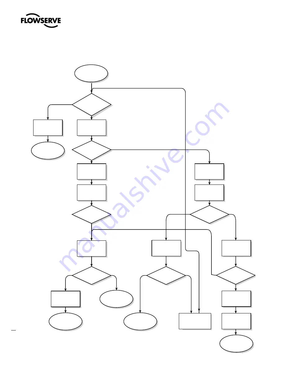
Figure 28:  StarPac 3 Pressure Sensor Troubleshooting Chart

Pressure reading

is incorrect

Is pressure

slightly off or

 saturated?

Saturated

Is reading

 saturated

 low or high?

Low

Slightly

off

Recalibrate

sensor

Make sure

sensor is

plugged in

Yes

Is sensor

working?

No

Swap sensors

Yes

No

Same problem

appear?

Problem is in 

wiring or board

Contact Factory

Replace

sensor

Replace

sensor

Check wire harness

for shorts or

contamination

Replace bad

O-rings

Tighten all

fittings

Check fittings

and O-rings

Yes

Is reading

correct?

No

Yes

No

Does reading

return to full

scale?

Reconnect

sensor

Yes

No

Does reading

go to 0?

Disconnect

sensor

High

Clean contacts

Summary of Contents for StarPac 3

Page 1: ...StarPac Intelligent Control System FCD VLENIM0066 02 02 10 flowserve com Experience In Motion USER INSTRUCTIONS Installation Operation Maintenance StarPac 3 Intelligent Control System FCD VLENIM0066 0...

Page 2: ......

Page 3: ...and Installation 14 8 1 Mounting to Flowserve Valtek Linear Mark One Valves 14 8 2 Mounting to Standard Flowserve Valtek Rotary Valves 14 8 3 Optional Flowserve Valtek Rotary Mounting Procedure 17 8...

Page 4: ...t 30 14 7 Keypad Assembly Replacement 31 14 8 Driver Module Assembly Replacement 31 14 9 Regulator Replacement 35 14 10 Checking or Setting Internal Regulator Pressure 35 14 11 Checking or Setting the...

Page 5: ...All Flowserve User Instruction Manuals are available at www flowserve com 1 3 Terms Concerning Safety The safety terms DANGER WARNING CAUTION and NOTE are used in these instructions to highlight parti...

Page 6: ...t be refitted Apart from the operating instructions and the obligatory accident prevention directives valid in the country of use all recognized regulations for safety and good engineering practices m...

Page 7: ...he vent assembly is located in the upper left side of the positioner The gaps around the assembly as noted by the arrows should be sealed for long storage Joints to be sealed A small desiccant package...

Page 8: ...system be aware that the center of gravity may be above the lifting point Therefore support must be given to prevent the valve from rotating Failure to do so can cause serious injury to personnel and...

Page 9: ...Connect the air supply and instrument signal lines 4 Quick check Prior to start up check the control valve by following these steps 1 Stroke the valve and observe the plug position indicator on the st...

Page 10: ...d brackets are securely fastened 8 If possible remove air supply and observe actuator for correct fail safe action 9 Check rubber actuator bellows for splits cuts or wear 10 Spray a soap solution arou...

Page 11: ...B 230 mA Group C 590 mA Group D 800 mA Overload protection Minimum 500 volt isolation 24 V power fuse protected Serial Interface Dual RS 485 ports Modbus Protocol USB Interface 2 0 mini B Modbus Prot...

Page 12: ...gs Table VI Positioner Specifications Deadband 0 1 full scale Repeatability 0 05 full scale Linearity 0 5 rotary 0 8 sliding stem full scale Air Consumption 0 3 SCFM 0 5 Nm3 hr 60 psi 4 barg Table VII...

Page 13: ...feedback loop which determines how much current to send to the electromagnet for a desired spool valve position The electromagnet in the feedback loop varies the nozzle flapper spacing which regulate...

Page 14: ...er will then make small null adjustments to fine tune the desired position and compensate for changes in dynamic loading A decrease in the command signal reverses the described actions causing a propo...

Page 15: ...insert through washers into the stem clamp Leave bolts loose 6 Slide the appropriate pin slot of the take off arm based on stroke length over the follower arm pin The appropriate stroke lengths are s...

Page 16: ...ttach bracket to actuator transfer case pad Leave these bolts slightly loose until final adjustments are made 6 Rotate take off arm so the follower pin will slide into the slot on the take off arm Adj...

Page 17: ...ck values were exceeded and the arm must be adjusted away from the positioners limits Return to step 2 and rotate the arm back approximately 10 degrees NOTE Remember to remove the air supply before re...

Page 18: ...ot direction of rotation WARNING If rotating in wrong direction serious damage will occur to the positioner and or linkage Check air action and stroke direction carefully before initiating operation 8...

Page 19: ...pneumatic side of the actuator regardless of air action The Output 2 port must be plugged 9 Wiring and Grounding Guidelines WARNING This product has electrical conduit connections in either thread si...

Page 20: ...RS 485 Communications RS 485 wiring requires the use of a shielded twisted pair cable which is grounded only at the source and not in the unit For maximum performance wire should have a characteristic...

Page 21: ...it isolated so that unex pected valve stroking will not adversely affect the process WARNING The following procedures may cause the valve to stroke causing pressures and temperatures to vary from thei...

Page 22: ...mode Normally the unit arrives from the factory set in the manual analog operating mode This means a command signal will position the valve the same as a traditional control valve providing a plug po...

Page 23: ...position jumper labeled JP3 There are 2 jumpers that must be moved together to set the voltage input range The jumpers are oriented vertically and with both jumpers in the upper position the input is...

Page 24: ...ing Address 1 Parity Odd Baud Rate 19 200 Modbus Communication Mode RTU RS 485 Termination Resistors Installed 11 2 Selecting Correct Address Setting If the StarPac 3 unit is the only StarPac unit on...

Page 25: ...e next section Using more than two termination resistors in a network can cause the RS 485 communications to operate erratically or fail On the top electronic board there are two termination jumpers f...

Page 26: ...nge 14 2 Mechanical Subsystem Maintenance Refer to the appropriate Flowserve Installation Operation Maintenance IOM instructions for details on repair and maintenance of the control valve actuator com...

Page 27: ...pin for excess wear and replace if needed The take off arm attached to the stem clamp must be firmly secured to the stem clamp and perpendicular to the actuator stem If this takeoff arm is canted or...

Page 28: ...or into the sensor port making sure the O ring or gasket remains properly in place while tightening the sensor Tighten the sensor until it seats metal to metal at the gasket section of the sensor port...

Page 29: ...cables may be potted inside the fitting at the bottom of the positioner housing To remove the cable it will be necessary to cut the existing cable on both sides of the fitting The fitting will need t...

Page 30: ...from the main PCB board and remove the keypad 4 Disconnect the red and yellow thermocouple wire Refer to Figure 11 5 Loosen the tubing nuts on both ends of the thermocouple assembly refer to Figure 12...

Page 31: ...he main PCB board Unplug the keypad ribbon cable from the main PCB board and remove the keypad 5 Install the new keypad assembly by first plugging the keypad ribbon cable into the connector on the mai...

Page 32: ...alve cover Figure 14 Spool Valve Cover Assembly 5 Remove the Phillips head screw that attaches the driver module to the main housing Figure 15 Be careful not to lose the nylon washer as the screw is r...

Page 33: ...15 of this manual 11 Disconnect the flexible tubing from the barbed fitting at the driver module assembly see Figure 16 12 Use the 1 4 nutdriver to remove the barbed fitting from the driver module ass...

Page 34: ...around the screw using an RTV sealant 20 Insert a driver to housing screw into the driver housing through the counterbored hole in the positioner main housing Tighten with a Phillips screwdriver 21 Re...

Page 35: ...ctrostatically sensitive devices 1 Make sure valve is bypassed or in a safe condition 2 Disconnect the power and air supply to the unit 3 Remove the main cover 4 Remove the two keypad retaining screws...

Page 36: ...ubing a few inches in length each 8 Position the barbed tee between the internal regulator and the driver module by connecting the 1 16 flexible tubing found in the positioner to one side of the barbe...

Page 37: ...rve precautions for handling electrostatically sensitive devices 1 Make sure valve is bypassed or in a safe condition 2 Disconnect power and air supply from the positioner 3 Remove the main cover 4 Re...

Page 38: ...y several times and recheck the minimum pressure and re adjust if necessary to ensure that the pressure has settled within the range specified 16 When the pressure is set remove the air supply 17 Remo...

Page 39: ...t and set aside Figure 19 3 Remove the molded filter element by pulling it straight out of the chamber cover vent piece 4 Install O ring into base of chamber cover vent piece as shown in Figure 19 5 P...

Page 40: ...e housing base as a register Figure 15 Slide the block toward the driver module until the two retaining holes line up with the threaded holes in the base 9 Install two spool valve screws and tighten s...

Page 41: ...nect to the main PCB assembly 11 Re install the main PCB assembly following the instructions found in section 14 15 of this manual 12 Re install the keypad Insert the two retaining screws and tighten...

Page 42: ...ostatically sensitive devices 1 Make sure the valve is bypassed or in a safe condition 2 Disconnect the power and air supply to the unit 3 Remove the main cover 4 Remove the keypad by removing the two...

Page 43: ...bosses in the housing Make sure all wires are clear and do not get pinched between bottom circuit board and the housing bosses 15 While holding the metal pressure sensor board stiffener in place inse...

Page 44: ...rews see Figure 5 11 Reconnect the field wiring to the customer interface board terminals 12 Install the keypad assembly and secure with the two retaining screws 13 Reinstall all covers 15 Optional Ve...

Page 45: ...ting into the spool valve cover part no 179477 Connect the necessary tubing piping to this fitting to route the exhausted na tural gas to a safe environment The maximum allowable back pressure in the...

Page 46: ...essure Regulator 5 to 30 psig Includes 2 O rings 37 Spool Valve Shroud 12 Screw Regulator Plate to Housing 4 38 Spool Valve Cover 13 Hex Barbed Fitting with Captive O ring 39 Hydrophobic Filter Spool...

Page 47: ...rol System FCD VLENIM0066 02 02 10 flowserve com 35 2 3 4 6 7 8 9 10 11 12 13 14 15 16 17 18 19 20 21 22 23 24 25 26 27 28 29 30 31 32 33 34 36 37 38 39 40 41 42 43 44 45 46 47 48 49 50 51 1 5 Figure...

Page 48: ...48 O ring Feedback Shaft 1 49 Torsion Spring 1 50 E ring 1 Kit 6 Feedback Shaft Kit Namur P N 215805 999 000 46 Feedback Shaft 1 47 Screw Spring to Feedback Shaft 1 48 O ring Feedback Shaft 1 49 Torsi...

Page 49: ...9 135437 135430 135433 0 75 135429 135438 135430 137212 0 88 135429 135439 135430 137213 135431 135434 1 12 135430 137214 135431 137218 1 50 135431 137216 1 75 135431 137217 Standard All rotary valves...

Page 50: ...83888 83901 Item No Description Quantity Kit 2 Spiral Wound Gasket Replacement Kit Part No 134560 999 000 6 Environmental O ring Viton 2 8 Environmental O ring Viton 4 10 O ring seal Viton 2 20 Envir...

Page 51: ...mote Mount Pressure Sensor Hardware Kit with Purge and Isolation Valves Part No 134558 999 000 3 Swagelok nut 4 4 Swagelok ferrules 4 15 Temperature extended fitting 2 16 Purge valve 2 17 Isolation va...

Page 52: ...urations Boss on valve body 12 11 10 8 9 8 1 7 6 5 4 3 2 1 Electrical connection cable 2 Tubing 0 035 wall thickness 3 Tube nut 4 Tube ferrule set 5 Sensor nut 6 Environmental O ring 7 Sensor fitting...

Page 53: ...fitting 12 O ring seal 15 Temperature extended fitting 16 Purge Valve 17 Isolation valve 18 Wet leg tubing 0 065 inch wall 19 Adapter fitting 20 Environmental O ring 21 O ring seal 21 Temperature Sens...

Page 54: ...IX 316 Stainless Steel Tubing Description Number Pressure sensor wire tubing 0 50 inch diameter 0 035 inch thick 063200 150 000 Extended temperature wet leg tubing 0 50 inch diameter 0 065 inch thick...

Page 55: ...work connections for correct positive and negative connections Individual units not properly wired Begin with shortest RS 485 run checking polarity and communication continue checking units throughout...

Page 56: ...h Low Slightly off Recalibrate sensor Make sure sensor is plugged in Yes Is sensor working No Swap sensors Yes No Same problem appear Problem is in wiring or board Contact Factory Replace sensor Repla...

Page 57: ...and hold down the ZERO 0 key on the keypad while turning the 24V power ON 3 Release the key after the display has booted and is active approx 5 seconds The following conditions are set upon re initia...

Page 58: ...oups A B C D 30 Explosionproof FM Class I Div 1 Groups B C D 31 Feedback Shaft DD Shaft 316 SS Valtek Standard D6 D6 Namur Shaft 316 SS VDI VDE 3845 N6 Conduit Connections 1 2 NPT E E M20 M Action Fou...

Page 59: ......

Page 60: ...e variety of industrial service conditions Although Flowserve can and often does provide general guidelines it cannot provide specific data and warnings for all possible applications The purchaser use...

Reviews: