background image

Limitorque 

®

 Master StationI V EEP-SN4001  FCD LMENIM5010-00-AQ – 03/19

57

flowserve.com

Diagnostics

8.1 Main Menu

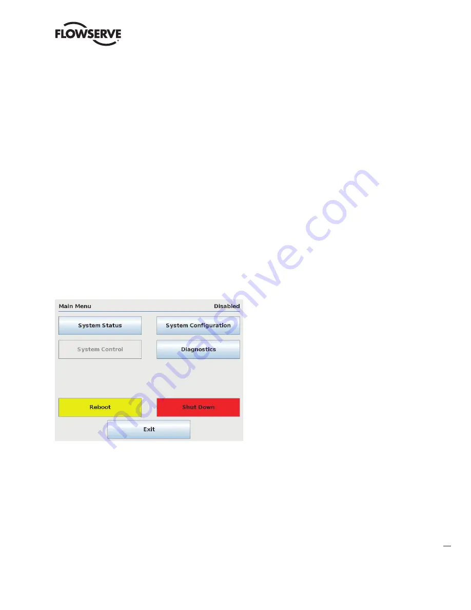
Upon successful login as a user assigned to either Configure or Administrator role level, the Diagnostics button on the 

Main Menu screen will be present. Press the Diagnostics button to advance to the Diagnostics menu.

Figure 8.1 – Main Menu

Summary of Contents for MASTER STATION IV EEP-SN4001

Page 1: ...Experience In Motion USER INSTRUCTIONS Installation Operation Maintenance MASTER STATION IV EEP SN4001 FCD LMENIM5010 00 AQ 03 19...

Page 2: ...Limitorque Master Station IV EEP SN4001 FCD LMENIM5010 00 AQ 03 19 2...

Page 3: ...1 5 2 1 Network Status 21 5 2 2 MOV Status 22 5 2 3 MSIV Status 22 5 2 4 MOV Data 23 6 System Control 24 6 1 Main Menu 24 6 2 System Control 24 6 2 1 MOV Control 25 6 2 2 Emergency Shutdown 26 7 Syste...

Page 4: ...Figure 6 2 MOV Control Menu 25 Figure 6 3 Control Relays 25 Figure 6 4 Emergency Shutdown 26 Figure 6 5 Emergency Shutdown in Progress 26 Figure 6 6 Emergency Shutdown Termination 27 Figure 7 1 Syste...

Page 5: ...8 Figure 8 4 Comm FC Logger 59 Figure 8 5 Debug Serial Port 59 Figure 8 6 Polling Statistics 60 Figure 9 1 Rear Panel On Off Switch Fuse and Power Input Terminals 62 Tables Table 4 1 Network Channel A...

Page 6: ...o login Four user role levels are configurable for each user 1 View 2 Control 3 Configure and 4 Administrator Each role includes the rights of the lesser roles i e Control includes View s rights and C...

Page 7: ...hing any part of the screen will load the Enter User name screen Figure 1 2 NOTE If the screen is blank and the green power LED is illuminated the MSIV is in screen saver mode Touch the display to exi...

Page 8: ...see the Main Menu Figure 1 4 Figure 1 4 Main Menu From here the menu options are displayed based on the current user role Each button represents a separate logical section of the Master Station SYSTE...

Page 9: ...Protocols 5 1 MSIV to Field Units 5 1 1 Modbus RTU 5 1 1 1 EIA 485 RS 485 physical layer 5 1 1 2 Bi directional redundant loop or multi drop network topologies 5 1 1 3 Maximum communication rate of 3...

Page 10: ...Limitorque Master Station IV EEP SN4001 FCD LMENIM5010 00 AQ 03 19 10 2 Function Flowchart The following flowchart graphics illustrate the main functional categories of the MSIV...

Page 11: ...Limitorque Master StationI V EEP SN4001 FCD LMENIM5010 00 AQ 03 19 11 flowserve com Figure 2 1 MSIV Functional Flowchart System Configuration branch continued on next page...

Page 12: ...Limitorque Master Station IV EEP SN4001 FCD LMENIM5010 00 AQ 03 19 12 System Configuration branch continued...

Page 13: ...e to Disabled startup mode to Active and redundancy mode to desired setting 9 Press the Back button and in the System Configuration page select User Administration 10 Set up user accounts 11 Select MO...

Page 14: ...itch the MSIV DC power supply ON or OFF 2 FUSE Housing of the fuse used to protect the DC power input Use a 5x20mm 2 5 amp 250V fuse 3 EARTH GROUND Chassis ground using a 10 32 grounding screw The Mas...

Page 15: ...r channel B of the MOV network using 6 32 terminal screws See table below for connection details Table 4 2 Network Channel B Connection Connector MX QX UEC 3 DDC DATA A2 5 TB3 D M DATA A2 4 TB3 D M Sh...

Page 16: ...emale 8 MOV TCP IP Ethernet connector for future development not currently placed Intended for use with actuators that are equipped with Modbus TCP IP add on adapter 9 WEB ETHERNET Ethernet port for f...

Page 17: ...r loop mode this is the total length between operating field units If a field unit loses power the relays internal to the field unit connect the A1 Channel to the A2 Channel which effectively doubles...

Page 18: ...llel to the same MOV RS 485 network as shown below The redundant modules can be located at any position in the network but Configure one module as Active and one as Standby as explained in section 7 2...

Page 19: ...ules MSIV Module Connector MX QX Network UEC 3 DDC Network Hot Active Channel A Data 13 TB4 D S Channel A Data 14 TB4 D S Shield GND N C Standby Channel B Data 5 TB3 D M Channel B Data 4 TB3 D M Shiel...

Page 20: ...ccessful login as a user assigned to any role level the System Status button on the Main Menu screen will be present Simply touching the System Status button will advance the HMI display to the System...

Page 21: ...Only those MOVs that have been activated will be displayed See MOV Network Config in System Configuration to activate desired MOVs Figure 5 3 Network Status The numeric buttons represent addressed MOV...

Page 22: ...he MOV communication channels and the Modbus holding registers that have been selected to be mapped to the PLC DCS data table Figure 5 4 MOV Status Screen 5 2 3 MSIV Status The MSIV Status screen prov...

Page 23: ...EP SN4001 FCD LMENIM5010 00 AQ 03 19 23 flowserve com 5 2 4 MOV Data The MOV Data menu displays detailed unit information of network MOVs including Unit Data QA Data Software and Options the unit has...

Page 24: ...re or Administrator role the System Control button on the Main Menu will be selectable if the MSIV is in Active mode Pressing the System Control button will advance the user to the System Control menu...

Page 25: ...V operation for the latest generation smart actuators MOV control relays can also be energized from this screen if the relays are configured for network control within the MSIV Figure 6 2 MOV Control...

Page 26: ...down As shown in figure 6 4 two options are available Initiate Emergency Shutdown and Terminate Emergency Shutdown Once an emergency shutdown has completed and is no longer needed the emergency shutdo...

Page 27: ...4001 FCD LMENIM5010 00 AQ 03 19 27 flowserve com When an emergency shutdown is terminated the Emergency Shutdown Termination in Progress screen will be displayed until the procedure is complete Figure...

Page 28: ...the user to the System Configuration menu 7 2 System Configuration The System Configuration menu allows the user to view configure the main settings within the Master Station Figure 7 1 System Config...

Page 29: ...l For example if one MOV is configured for 9600 baud rate but another MOV is configured for 18200 baud rate it is impossible for the Auto Detect feature to add both MOVs to the network configuration S...

Page 30: ...he Version screen displays the Master Station s current software version information Figure 7 3 Software Version Information 7 2 1 2 Language The language menu allows the user to set the unit s displa...

Page 31: ...t the unit s clock parameters including the current time Figure 7 5 System Clock Settings Additionally the MSIV clock can be set to a specific time zone by selecting the Time Zone button in the Clock...

Page 32: ...ers from resuming an authorized user s session If this setting is Disabled the MSIV will return directly to the menu and session which were active prior to the screen saver being activated This is the...

Page 33: ...the configuration files operation is restored The Standby unit operation is restored shortly after Figure 7 9 Configuration Transfer Lockout 7 2 3 Change MOV Tags This menu allows the user to set or m...

Page 34: ...on the user Administration menu The MSIV will step through a form of entering a username password confirming the password and confirming the add user action All new users default to Viewer privileges...

Page 35: ...he User Administration menu Figure 7 13 User Settings Menu 7 2 4 4 Change Password To change a password for a user account press the Change Password button on the User Administration menu A listing of...

Page 36: ...d save settings as default when prompted Figure 7 16 Configure DCS Serial Port 7 2 5 DCS Configuration The DCS Configuration menu allows the user to configure communication port parameters to successf...

Page 37: ...the settings Note that if 2 redundant modules are used each module must be configured with a unique IP address Note use port 502 for Modbus TCP IP communications Figure 7 17 Configure DCS Ethernet Por...

Page 38: ...Bit Definitions Bit Number Modbus Bit Address MX DDC 129 128 Opened 130 129 Closed 131 130 Stopped in mid travel 132 131 Opening 133 132 Closing 134 133 Valve jammed 135 134 Not in remote 136 135 Comb...

Page 39: ...153 Not used 155 154 Network emergency shutdown ESD is active 156 155 Local emergency shutdown is active 157 156 Field unit microprocessor has reset since the last poll 158 157 MX in stop mode 159 158...

Page 40: ...ed 208 207 PB DP board present From the DCS the user must address the MSIV and poll according to the FC 02 data table See the following example of a request response exchange between the DCS and MSIV...

Page 41: ...ng the Next button will advance the screen to a sample data table Figure 7 20 FC 03 Read Holding Registers Menu Figure 7 21 FC 03 Example Data Table Note Data table shown with registers 8 9 10 and 11...

Page 42: ...te 2 0044h equals 68 decimal or 0000 0000 0100 0100 actuator stopped between limits in local mode Table 7 4 Function Code 03 Holding Registers Register Description Meaning 10 Fault Register 16 Bits of...

Page 43: ...ult Open Inhibit Terminal 34 Bit 10 User Input 2 Default Close Inhibit Terminal 35 Bit 11 Remote Stop Input Terminal 26 Bit 12 Remote Open Input Terminal 25 Bit 13 Remote Close Input Terminal 27 Bits...

Page 44: ...plications Only 49 TP_STOP_POSITION Special Applications Only 50 TP_SAMPLE Special Applications Only 51 TP_MID_T_HIGH Special Torque Applications Only 52 TP_MID_T_POS Special Applications Only 53 TP_M...

Page 45: ...ing a 15 command to force two coils starting with coil 1 with coil 1 ON and coil 2 OFF would result in the unit stopping since coil 2 is forced OFF after coil 1 is forced ON To prevent inadvertent sto...

Page 46: ...C 8DFF Error Check CRC Note 1 0010h equals coil address 0001 0001b field unit 5 coil 1 Note 2 FF00h requests the coil to be ON 0000h requests the coil to be OFF Example of force multiple coils command...

Page 47: ...n below Please note that a unique table is created starting at register 45001 Specific field unit registry convention is as follows DCS Command Write Register MOV address 1 selected number of register...

Page 48: ...0h requests the register to be preset with 1280d Start Network ESD Example of a two command write to a single register Move To command Move an actuator at addr4ess 45 to 42 open by first writing the v...

Page 49: ...ers 45050 45051 and 45052 Query 011013B90003060300030003006ABB Response 011003B900035569 Table 7 11 Function code 16 message breakdown Query Response 01 MSIV Unit Address 01 MSIV Unit Address 10 Funct...

Page 50: ...ways be taken to properly change these values An improper value written to a register can cause undesirable MOV behavior Note Null command the field unit takes no action when this command is received...

Page 51: ...ication Figure 7 26 General DCS Settings defaults shown 1 1 The MS1 Legacy Mapping Mode setting can be Enabled Disabled for use of the A B style mapping as explained in section 7 2 5 3 1 FC 02 Read In...

Page 52: ...The Poll Priority button allows the user to set the poll cycle interval for each activated MOV After changing configurations press Accept to save the settings Note MOV Network Configuration is disable...

Page 53: ...ile Manager is disabled when the unit is in Active mode To turn off Active mode go to the System Configuration menu and select the Redundant Config button Under Requested Mode select the Disabled butt...

Page 54: ...ith the new imported file Figure 7 31 Import Configuration File 7 2 7 2 Load Tag File The Load Tag File menu allows the user to access the file chooser and select an MOV tag name file from a connected...

Page 55: ...configuration events network status or MOV status polling activity In addition all captured events are defined numbered and time stamped in order to maintain the logged data Figure 7 32 Export Event...

Page 56: ...Factory Defaults To return the MSIV configuration settings to factory defaults press the Restore Factory Defaults button at the bottom of the File Manager menu A confirmation box will appear to confi...

Page 57: ...serve com 8 Diagnostics 8 1 Main Menu Upon successful login as a user assigned to either Configure or Administrator role level the Diagnostics button on the Main Menu screen will be present Press the...

Page 58: ...g Stats Figure 8 2 Diagnostics Menu Figure 8 3 Event Log The Event Logger allows the user to display the last 20 events that were recorded Every entry is defined numbered and time stamped in order to...

Page 59: ...er is designed for local diagnostic purposes only While the logger is active the MSIV will expe rience reduced communication performance When not needed for diagnostics the logger channels should be d...

Page 60: ...he polling history of each activated MOV on the network This menu displays the total number of polls number of errors and error rate Press Reset MOV to clear the polling stats for the currently select...

Page 61: ...y If the LED is off there is not transmitter activity WEB LINK LED indicating the status of the WEB ethernet port LINK ON port connected to a 10 100 network OFF port is not connected to a 10 100 netwo...

Page 62: ...gs 4 Check host system settings 5 Test communication cable s Problem Unable to establish communications with DCS Modbus TCP IP port 1 Confirm IP address settings a ping command from some point on the...

Page 63: ...Limitorque Master StationI V EEP SN4001 FCD LMENIM5010 00 AQ 03 19 63 flowserve com Notes...

Page 64: ...product is designed to perform its intended function safely during its useful life However the purchaser or user of Flowserve products should be aware that Flowserve products might be used in numerou...

Reviews: