background image


HWMA2 USER INSTRUCTIONS ENGLISH - 06/16


Page 39 of 39  


Your  Flowserve factory contacts: 
 

Flowserve (Austria) GmbH 

Industriestraße B6 

2345 Brunn am Gebirge 

Austria 


Telefon: 


+43 2236 31530 

Fax:       


+43 2236 33430 

E.mail:   

      [email protected]


FLOWSERVE REGIONAL 
SALES OFFICES: 


USA and Canada 

Flowserve Corporation 
5215 North O’Connor Blvd. 
Suite 2300 
Irving, Texas 75039-5421, USA 
Telephone: +1 937 890 5839 


Europe, Middle East, Africa 

Flowserve Corporation 
Parallelweg 13 
4878 AH Etten-Leur 
The Netherlands 
Telephone: +31 76 502 8100 


Latin America 

Flowserve Corporation 
Martín Rodriguez 4460 
B1644CGN-Victoria-San 

Fernando 
Buenos Aires, Argentina 
Telephone: +54 11 4006 8700 
Telefax: +54 11 4714 1610 


Asia Pacific 

Flowserve Pte. Ltd. 
10 Tuas Loop 
Singapore 637345 
Telephone: +65 6771 0600 
Telefax: +65 6862 2329


Компания ПромХимТех – официальный дистрибьютор

насосов Flowserve, запасных частей Флоусерв
www.promhimtech.ru  тел. 8 800 250-01-54

e-mail: [email protected]

Summary of Contents for IDP HWMA2

Page 1: ...allation Operation Maintenance 2 STAGE VERTICAL INLINE Original Instructions PCN 71569277 06 16 E Компания ПромХимТех официальный дистрибьютор насосов Flowserve запасных частей Флоусерв www promhimtech ru тел 8 800 250 01 54 e mail zakaz promhimtech ru ...

Page 2: ...6 4 7 FINAL SHAFT ALIGNMENT CHECK 16 5 0 COMMISSIONING START UP OPERATION AND SHUTDOWN 16 5 1 PRECOMMISSIONING PROCEDURE 16 5 2 PUMP LUBRICANTS 16 5 3 IMPELLER CLEARANCE 22 5 4 DIRECTION OF ROTATION 22 5 5 GUARDING 22 5 6 PRIMING AND AUXILIARY SUPPLIES 22 5 7 STARTING THE PUMP 22 5 8 OPERATION 23 5 9 STOPPING AND SHUTDOWN 23 5 10 HYDRAULIC MECHANICAL AND ELECTRICAL DUTY 23 6 0 MAINTENANCE 24 6 1 G...

Page 3: ...ating to machinery and equipment and the satisfactory provision of technical documents and safety instructions Where applicable this document incorporates information relevant to these Directives To establish Approvals and if the product itself is CE Marked check the serial number plate and the Certification 1 3 Disclaimer Information in these User Instructions is believed to be reliable In spite ...

Page 4: ... and training All personnel involved in the operation installation inspection and maintenance of the unit must be qualified to carry out the work involved If the personnel in question do not already possess the necessary knowledge and skill appropriate training and instruction must be provided If required the operator may commission the manufacturer supplier to provide applicable training Always c...

Page 5: ...as experienced temperatures over 250 C 482 ºF partial decomposition of fluoro elastomers example Viton will occur In this condition these are extremely dangerous and skin contact must be avoided GUARDS MUST NOT BE REMOVED WHILE PUMP IS OPERATIONAL THERMAL SHOCK Rapid changes in the temperature of the liquid within the pump can cause thermal shock which can result in damage or breakage of component...

Page 6: ...led depending on material and construction variant check which is lower T6 T5 T4 T3 T2 T1 85 C 185 F 100 C 212 F 135 C 275 F 200 C 392 F 300 C 572 F 450 C 842 F Consult Flowserve Consult Flowserve 115 C 239 F 180 C 356 F 275 C 527 F 400 C 752 F The table only takes the ATEX temperature class into consideration Pump design or material as well as component design or material may further limit the ma...

Page 7: ...ss of a seal barrier fluid or external flush the fluid must be monitored If leakage of liquid to atmosphere can result in a hazard the installation of a liquid detection device is recommended 1 6 4 7 Maintenance to the centrifugal pump to avoid the hazard CORRECT MAINTENANCE IS REQUIRED TO AVOID POTENTIAL HAZARDS WHICH GIVE A RISK OF EXPLOSION The responsibility for compliance with maintenance ins...

Page 8: ...HWMA2 USER INSTRUCTIONS ENGLISH 06 16 Page 8 of 39 1 7 Warning label ...

Page 9: ...tion of equipment noise level so that you can take the appropriate action in your plant Pump noise level is dependent on a number of operational factors flow rate pipework design and acoustic characteristics of the building and so the values given are subject to a 3 dBA tolerance and cannot be guaranteed Similarly the motor noise assumed in the pump and motor noise is that typically expected from ...

Page 10: ... following conditions Equipment is located in a free field above a reflecting plane in which the reductionin noise level in all directions is 6db in each octave band for each doubling of distance Background noise is 10dB minimum below all noise levels in each octave band The values shown are at a distance of 1 meter horizontally from the major pump surface and 1 5 meters above the floor using a st...

Page 11: ...HWMA2 USER INSTRUCTIONS ENGLISH 06 16 Page 11 of 39 1 10 CE Declaration ...

Page 12: ...25kg 55lb Fully trained personnel must carry out lifting in accordance with local regulations The driver and pump weights are recorded on their respective nameplates 2 4 Storage If the unit will not be put immediately into service it should be stored in a dry room To avoid any damage during the storage period the influence of any low or high frequency vibration must be totally inhibited If the pum...

Page 13: ... radial vaned semi open impeller is used to ensure optimal performance 3 4 Performance and operating limits In the interest of operator safety the unit must not be operated above the nameplate conditions Such operation could result in unit failure causing injury to operating personnel Consult instruction book for correct operation and maintenance of the pump and its supporting components 4 0 INSTA...

Page 14: ... the motor to the pump not the pump to the motor Alignment of the motor is achieved by using the adjustment screws 4 4 1 Permissible misalignment limits at working temperature When checking parallel alignment the total indicator read out TIR shown is twice the value of the actual shaft displacement The pump is only pre aligned Carefully check and readjust alignment before start of the unit Take ou...

Page 15: ...Fitting an isolator and non return valves can allow easier maintenance Never throttle pump on suction side and never place a valve directly on the pump inlet nozzle A non return valve shall be located in the discharge pipework to protect the pump from excessive back pressure and hence reverse rotation when the unit is stopped Piping and fittings shall be flushed before use To avoid damages of the ...

Page 16: ... piping to the pump rotate the shaft several times by hand to ensure there is no seizure and all parts are free Recheck the coupling alignment as previously described to ensure no pipe strain If pipe strain exists correct piping 5 0 COMMISSIONING START UP OPERATION AND SHUTDOWN These operations must be carried out by fully qualified personnel 5 1 Precommissioning procedure a The bearing housing mu...

Page 17: ...e that enough oil remains in the reservoir e If necessary the oil level can be adjusted by refering to section 5 2 4 Oil level 5 2 3 Oil level The correct oil level is in the middle of the oil sight glass and shall be checked when pump is not in operation Periodically check if the lubricating oil is mixed with any condensed water Careful opening of the oil drain during a stop of the pump will show...

Page 18: ...il temperature in the bearing itself is about 10 C Δ 18 F higher than the oil temperature at the bearing housing On the following table the oil viscosity is given at 40 C 104 F Determining the correct lubricating oil one must take into consideration that all bearings will have higher temperatures during the first 20 service hours In constant operation the bearing temperature will decrease about 10...

Page 19: ...an HN32 Wiolan HS32 46 200 hours 2000 hours or at least every 6 months 46 LSO 32 Synthetic oil Mobil Nuto H32 Mobil DTE13M Mobil DTE24 Shell Tellus 32 Shell Turbo T32 68 200 hours 2000 hours or at least every 6 months 68 Aral Vitam GF 68 Mobil Nuto H46 Mobil DTE15M Mobil DTE25 Aral Vitam GF 46 NUTO H46 Oil Bath and Purge Oil Mist Lubrication BP Energol HL68 BP Energol HLP68 Perfecto T68 OMV turb H...

Page 20: ...n System Company The bearing housing requires a minimum SCFM value as follows Ref No Bearing Reclassifier at Manifold Directional Reclassifier 3013 1 x 0 30 SCFM 3011 1 x 0 18 SCFM 77 700 622 The pressure in the bearing housing shall be 0 05 bar 0 74 psi 20 inches of water column A continuous lubrication should occur during operation and standby Pre Lubrication shall be performed at least 1h befor...

Page 21: ...systems 5 2 10 Oil change After first start up the oil shall be changed after 200 service hours Every further oil change shall take place after about 2000 service hours or at least every 6 month To change the oil use the following procedure f Open the oil drain on the bearing housing to remove the oil g Close the oil drain and fill in Oil through the vent connection on the bearing cover until the ...

Page 22: ...n Screw in an Eyebolt into the thread at the top of the shaft Use a lever or a crane to lift the shaft do it slowly the axial clearance is only a few millimetres h Measure again the dimension from the shaft nut to the end of the shaft i Take the mean value of the two dimensions and adjust the rotor to this value by turning the shaft nut The type of hydraulic is shown on the nameplate refer to sect...

Page 23: ...eezing point the pump and any cooling and flushing arrangements must be drained or otherwise protected For automatic start stop operation of the pump ensure that all steps described in chapter 5 6 5 7 5 8 and 5 9 are implemented in the control logic 5 10 Hydraulic mechanical and electrical duty This product has been supplied to meet the performance specifications of your purchase order however it ...

Page 24: ...ot spray air or compressed inert gas on skin Do not direct an air or gas jet towards other people Never use air or compressed inert gas to clean clothes Before working on the pump take measures to prevent an uncontrolled start Put a warning board on the starting device with the words Machine under repair do not start With electric drive equipment lock the main switch open and withdraw any fuses Pu...

Page 25: ...e parts 6 3 1 Ordering of spares When ordering spare parts we need the following information 1 pump type and pump size 2 serial number of the pump 3 number of the required spare parts 4 reference number and name of the part as listed in the part list or in the sectional drawing Example for HWMA2 pump HWMA2 serial number G202222 01 1 piece impeller Pos 2200 The serial number of each pump is indicat...

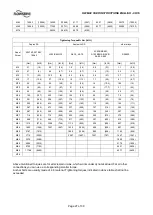
Page 26: ...6 3 4 M5 8 3 6 1 5 9 4 4 1 6 1 2 2 2 1 6 8 6 6 3 M6 14 2 10 5 10 1 7 4 2 8 2 1 3 7 2 7 14 9 11 M8 35 26 24 6 18 1 6 8 5 9 1 6 7 36 27 M10 68 50 48 35 13 7 10 1 18 3 13 71 52 M12 118 87 84 62 23 17 31 23 123 91 M14 187 138 133 98 37 27 50 37 195 144 M16 290 214 206 152 57 42 76 56 302 223 M18 335 247 295 218 80 59 106 78 421 311 M20 472 348 415 306 112 83 150 111 592 437 M22 644 475 567 418 151 111...

Page 27: ...69 143 105 82 60 38 28 50 37 M16 145 107 222 164 126 93 58 43 76 56 M18 201 148 308 227 176 130 82 60 106 78 M20 283 209 434 320 247 182 115 85 150 111 M22 387 285 473 349 337 249 157 116 202 149 M24 487 359 595 439 426 314 198 146 257 190 M27 716 528 716 528 602 444 292 215 379 280 M30 968 714 968 714 817 603 397 293 515 380 M33 1315 970 1008 744 1112 820 536 395 697 514 M36 1692 1248 1297 957 14...

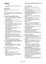
Page 28: ...sequence below using 30 of the tightening torque indicated in chapter 6 5 1 Stage 2 Torque the bolts following the illustrated sequence below using 60 of the tightening torque indicated in chapter 6 5 1 Stage 3 Torque the bolts following the illustrated sequence below using 100 of the tightening torque indicated in chapter 6 5 1 ...

Page 29: ...olt 6577 3 and pull off the stuffing box housing 4110 2 Pull off the deflector 2540 from the shaft after loosing the grub screw 6814 2 3 Unsecure shaft nut 2910 by loosing the cap screw 6579 3 4 Unscrew the shaft nut 2910 the hexagon head bolt 6577 4 and remove the bearing cover 1220 and 3260 Take care about labyrinth ring 4330 5 Now you can pull out the shaft assembly from the bearing housing Pul...

Page 30: ...and secure it with the grub screw 6814 3 4 Put in key 6700 3 and slip the thrust bearing assembly to the shaft 2100 5 Put in the key 6700 2 and mount the pumping ring 4223 at the line bearing side Take care of the O ring 4610 7 6 Now you can push the shaft assembly into the bearing housing 3200 7 Mount the distance sleeve 2460 and the deflector 2540 Secure the deflector with the grub screw 6814 2 ...

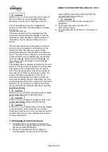
Page 31: ...eadjust it following procedure in section 5 3 1 Adjusting of the rotor Actions after start up Check all connections to the seal gland and the mechanical seal itself against leakage It is usual that at the seal faces a small leakage occurs after start up which decreases with the time of operation and should stop after the seal is run in period Check the temperature of the seal gland I slight increa...

Page 32: ... the mechanical seal without taking it apart Actions before first start up The pump will be delivered with correct vertical adjustment of the rotor Try to turn the rotor by hand If the rotor cannot be turned readjust it following procedure in section 5 3 1 Adjusting of the rotor The mechanical seal requires no adjustment anymore Check if the mounting plates are alreadyswung out Actions after start...

Page 33: ...r fluid The seal pot pressure must be maintained at the proper level If the seal pot pressure drops the system will begin to operate like a Plan 52 or unpressurized dual seal which does not offer the same level of sealing integrity Specifically the inner seal leakage direction will be reversed and the barrier fluid will over time become contaminated with the process fluid with the problems that re...

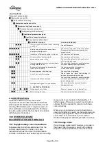
Page 34: ...ubmerged Check cut out system design Total head of system higher than differential head of pump Check discharge head and head losses in discharge pipe at the valve settings Check back pressure is not too high Total head of system lower than pump design head Throttle at discharge valve or ask Flowserve if the impeller can be trimmed Specific gravity of liquid different from design Consult Flowserve...

Page 35: ...s Check method of assembly possible damage or state of cleanliness during assembly and type of bearing used Damaged bearings due to contamination Check contamination source and replace damaged bearings C ELECTRICAL TROUBLES Wrong direction of rotation Reverse 2 phases on motor terminal box Motor running too slow Check motor terminal box connections 9 0 CERTIFICATION Certificates determined from th...

Page 36: ...Pumps a reference guide Europump Guide No 1 Europump World Pumps Elsevier Science United Kingdom 1999 Reference 2 Pump Handbook 2nd edition Igor J Karassik et al McGraw Hill Inc New York 1993 Reference 3 ANSI HI 1 1 1 5 Centrifugal Pumps Nomenclature Definitions Application and Operation Reference 4 ANSI B31 3 Process Piping ...

Page 37: ...owatt kW 1 34102 horsepower hp Pressure 2 bar bar 14 5 pounds in psi Rotational Speed revs per minute r min Stress Newton square millimetre N mm 145 0 pounds in psi Temperature degrees Celsius C 1 8 x C 32 degrees Fahrenheit F Torque Newton meter Nm 0 7376 pound feet lbf ft Unbalance gram millimeter g mm 0 001389 ounce inch oz in Vibration 3 millimetre second mm s 0 03937 inches second in sec Velo...

Page 38: ...ING MACHINE IMPORTANT NOTES PLEASE NOTE THAT WARRANTY EXPIRES USE OF NON GENUINE FLOWSERVE AUSTRIA PARTS FOR MAINTENANCE AND REPAIRS NO USE OF OUR SERVICE PERSONAL IN CASE OF REPAIRS DURING WARRANTY PERIOD RECOMMENDATION PLEASE ASK FOR OUR SPECIAL RATES PLEASE ALSO ASK OUR SERVICE PERSONAL ABOUT REPAIRING AND SERVICING YOUR PUMPS AFTER THE WARRANTY PERIOD Please quote your service Name of Company ...

Page 39: ...Telephone 1 937 890 5839 Europe Middle East Africa Flowserve Corporation Parallelweg 13 4878 AH Etten Leur The Netherlands Telephone 31 76 502 8100 Latin America Flowserve Corporation Martín Rodriguez 4460 B1644CGN Victoria San Fernando Buenos Aires Argentina Telephone 54 11 4006 8700 Telefax 54 11 4714 1610 Asia Pacific Flowserve Pte Ltd 10 Tuas Loop Singapore 637345 Telephone 65 6771 0600 Telefa...

Reviews: