HWMA2 USER INSTRUCTIONS ENGLISH - 06/16
Page 13 of 39
This also includes the liquids and or gases in the
"seal system" or other utilities.
Make sure that hazardous substances are
disposed of safety and that the correct personal
protective equipment is used. The safety
specifications must be in accordance with the current
regulations at all times.
3.0 DESCRIPTION
3.1 Configuration
The model HWMA2 belongs to Flowserves family of
API 610 vertical inline pumps.
The hydraulics are designed for operating flexibility
and consist of:
•
a semi open radial vaned impeller to guarantee
optimum performance
•
a circular volute with a single caned diffuser to
minimize hydraulic forces
The pump unit is available in two stage opposed
impeller configuration. For low NPSHA applications
an inducer is available.
The sense of rotation of the pump is
clockwise (CW), looking from the coupling to the shaft
end of the pump.
3.2 Nomenclature
Example:
2x3x12HWMA2 - Ind.
2
Discharge flange in inch
3
Suction flange in inch
12
max. impeller size in inch
2
2 stage
Ind
indicates Inducer as option
3.3 Design of major parts
3.3.1 Pump casing
Vertical inline design with flanged suction elbow and
integrated baseplate. It is directly flanged to the motor
stand, which itself is flanged to the motor. Back pull
out design for easy maintenance, so the casing
remains on its foundation in case of repair.
3.3.2 Hydraulics
A circular volute in combination with a single caned
diffuser is inserted into the pump casing. A radial
vaned semi open impeller is used to ensure optimal
performance.
3.4 Performance and operating limits
In the interest of operator safety
the unit must not be operated above the nameplate
conditions. Such operation could result in unit failure
causing injury to operating personnel. Consult
instruction book for correct operation and
maintenance of the pump and its supporting
components.
4.0 INSTALLATION
Equipment operated in hazardous locations
must comply with the relevant explosion protection
regulations, see section 1.6.4,
Products used in
potentially explosive atmospheres.
4.1 Location
The pump should be located to allow room for
access, ventilation, maintenance and inspection with
ample headroom for lifting and should be as close as
practicable to the supply of liquid to be pumped.
Refer to the general arrangement drawing for the
pump set.
4.2 Part Assemblies
The pumps are delivered completely mounted and
prealigned with the motor. Also the shaft seal is in the
correct position. Final alignment after complete
installation is necessary. If drivers and/or seal systems
are delivered separately, follow the assembly
procedure in section 6.8.
4.3 Foundation
The foundation shall be located on a place that allows
a minimum of pipe work and that is easily accessible
for inspection during operation. According to the
environment the foundation may consist of concrete
or of steel. It must be rigid and heavy enough to
absorb normal vibrations and shocks.
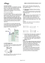
4.3.1 Horizontal alignment of the baseplate
Horizontal alignment is done with levelling screws.
Use a spirit level for correct horizontal alignment of
the baseplate.
The max. misalignment is 0.5 mm/m
baseplate length.


