


HDX USER INSTRUCTIONS ENGLISH 85392696 - 01/11
Page 43 of 60
i) Lift and install lower halves of thrust and line
bearing housings against their respective seats
on casing brackets. Tighten all bolting.
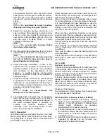
j) Pour a small amount of lubricating oil on lower
halves of sleeve bearing linings. Raise shaft a
slight amount and roll in lower halves of sleeve
bearings. Position oil rings correctly.
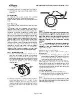
k) Pour a small amount of oil on shaft journal
bearings and install upper halves of sleeve
bearings. Install and tighten calibrated screws.
l) Check that rotor turns freely by hand.
m) Apply a liquid gasket to bearing body joint faces
and install upper halves of thrust and line bearing
housings. Secure with bolting and dowels. Take
care to position correctly in their respective seats,
all oil seals and labyrinth rings.
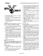
n) Set oil shields on shaft by pushing them against
labyrinths and withdrawing them about 3 mm.
Secure with set screws.
o) Fit “O” ring in place, install thrust bearing outer
cover and tighten bolting.
p) Install fan guard and fan, if any.
q) Check rotor end float. This should be 0.05 to 0.15
mm.
r) Install nuts securing mechanical seal plate
assembly to stuffing box at both ends of pump.
Tighten nuts evenly.
s) Finally set seal assemblies according the
manufacturer’s instructions.
t) Turn rotor by hand to ensure there are no rubs or
binding.
6.9.3.3 KTB
a) Install all oil shields together with respective
labyrinth rings from each end of shaft, in their
respective position. Fit “O” rings in labyrinth rings.
Do not tighten oil shield set screws.
b) Lift and install lower halves of thrust and line
bearing housings against their respective seats
on stuffing box brackets. Tighten all bolting.
c) Pour a small amount of lubricating oil on lower
halves of sleeve bearing linings. Raise shaft a
slight amount and roll in lower halves of sleeve
bearings.
d) Pour a small amount of oil on shaft journal
bearings and install upper halves of sleeve
bearings.
e) Install thrust bearing inboard seal in two halves.
f) Install inboard shim.
g) Install thrust collar key and thrust collar.
h) Install locknut and pull up tight against thrust
collar, then fit securing screws to lock nut.
i) Install thrust bearings parts (split base rings,
leveling plates and shoes) according Kingsbury’s
instructions.
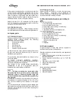
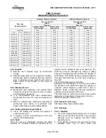
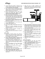
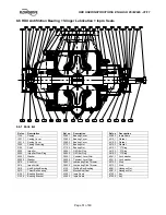
j) Check that rotor is axially centralized, and
establish total thrust end play, (about 0.28 mm)
by using shim or machining at inner face of thrust
bearing cover. See Fig. 6.5
Figure 6.6
k) Apply a liquid gasket to bearing body joint faces
and install upper halves of thrust and line bearing
housings. Secure with bolting and dowels. Take
care to position correctly in their respective seats,
oil seals and labyrinth rings.
l) Set oil shields on shaft by pushing them against
labyrinths and withdrawing them about 3 mm.
Secure with set screws.
m) Fit “O” ring in place, install thrust bearing outer
cover and tighten bolting.
n) Install nuts securing mechanical seal plate
assembly to stuffing box at both ends of pump.
Tighten nuts evenly.
o) Finally set seal assemblies according the
manufacturer’s instructions.
p) Turn rotor by hand to ensure there are no rubs or
binding.
6.9.4 Final assembly
a) Install coupling key and pump half coupling,
coupling nut and coupling nut set screws.
b) Check coupling/shaft alignment as described
under Section 4.5 and assemble coupling.
c) Install coupling guard.
d) Replace all auxiliary piping, instrumentation and
pipe plugs.
e) Install oilers and fill bearing housings to correct
oil level.
f) Refer to Section 5.
SHIMS


