background image

Rev


B


MN301030


11


of


14


ELECTRICAL


INSTALLATION


Step


Seven


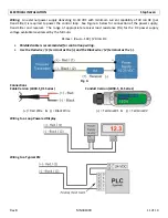
Wiring:


An


external


power


supply


delivering


13

30


VDC


with


minimum


current


capability


of


40


mA


DC


(per


transmitter)


is


required


to


power


the


control


loop.


See


Figure


A


below


for


connection


of


the


power


supply,


transmitter


and


receiver.


The


range


of


appropriate


receiver


load


resistance


(RL)


for


the


DC


power


supply


voltage


available


is


expressed


by


the


formula:


RLmax


=


(Vsup


10V)


/


20


mA


DC


Shielded


cable


is


recommended


for


control


loop


wiring.


Use


the


Red


wire


/


(1)


terminal


as


the


(+)


and


the


Black


wire


/


(2)


terminal


as


the


(

).


Fig.


A


Connections


Cable


Version


(LD30

S_01


Series)


(+)


=


Red


Wire


&


(

)


=


Black


Wire


Conduit


Version


(LD30

S_11


Series)


(+)


=


Terminal


#1


&


(

)


=


Terminal


#2


Wiring


to


a


Loop


Powered


Display


Wiring


to


a


Typical


PLC


Summary of Contents for DeltaSpan LD30 Series

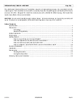
Page 1: ...n General Purpose External Mount Pressure Level Transmitter LD30 Series Manual Cable Series LD30 S_01 Conduit Series LD30 S_11 Flowline Inc 10500 Humbolt Street Los Alamitos CA 90720 Tel 562 598 3015 Fax 562 431 8507 www flowline com ...

Page 2: ...upply voltage ratings Permanent damage not covered by warranty will result This device is not designed for 120 or 240 volt AC operation Use only on 13 to 30 VDC Table of Contents Specifications 3 Dimensions 4 Technology 4 Material Compatibility 4 Safety Precautions 5 Components 6 Getting Started 7 How to convert Pressure into Liquid Height 7 How does Specific Gravity affect pressure transmitters 8...

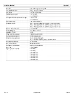
Page 3: ...psig maximum 150 psig over pressure S4_1 60 psig maximum 300 psig over pressure Power Requirement 13 to 30 VDC Output Signal 4 to 20 mA 2 wire Response Time 50 ms Max Loop Resistance 1300 Ohms 30 VDC Current consumption 38 mA maximum Electrical Connections S_01 Cable 9 length S_11 Conduit Housing with Terminal Block Process connection male NPT Enclosure rating NEMA 4X IP 66 Mounting Orientation Mo...

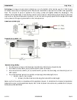
Page 4: ...ure of the gas is generated from the microprocessor Cable Series LD30 S_01 Conduit Series LD30 S_11 Material Compatibility The LD30 series is made of 316 Stainless Steel 316 SS 316L Stainless Steel 316L SS The Cable Version LD30 S_01 is provided with 3 0 91 m of cable The Conduit Version LD30 S_11 is provided with a junction box including a terminal strip and a NPT conduit The total length the sig...

Page 5: ...this product Use a proper sealant with all installations Always check for leaks prior to system start up Wiring and Electrical CAUTION A supply voltage of 13 to 30 VDC is used to power the LD30 series transmitter Electrical wiring of the sensor should be performed in accordance with all applicable national state and local codes Temperature and Pressure The LD30 series is designed for use in applic...

Page 6: ...ow DeltaSpan General Purpose External Mount Pressure Level Transmitter Part Number Maximum Pressure Range in Water Column Interface Connection LD30 S001 LD30 S011 05 psi 11 54 ft wc 3 52 m wc 9 2 7 m Cable Terminal Block in Housing LD30 S201 LD30 S211 15 psi 34 63 ft wc 10 56 m wc 9 2 7 m Cable Terminal Block in Housing LD30 S401 LD30 S411 30 psi 69 30 ft wc 21 12 m wc 9 2 7 m Cable Terminal Block...

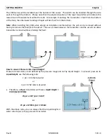
Page 7: ...installation method where the unit can be removed without having to remove the fluid from the vessel The use of valves between the transmitter and the vessel can allow transmitter removal without draining the fluid How to convert Pressure into Liquid Height Pressure transmitters are all defined by the pressure range and not by Liquid Height To convert pressure to Liquid Height use the following ra...

Page 8: ...psi x 2 31 psi 0 9 38 5 Note The above formula will always provide the Maximum Liquid Height for any pressure transmitter Example Compare the Maximum Liquid Height of a liquid with a SG 0 9 to one with a SG 1 0 SG 0 9 a 15 psi transmitter will have a Maximum Liquid Height 38 5 11 73 m SG 1 0 a 15 psi transmitter will have a Maximum Liquid Height 34 65 10 56 m A change in SG of 0 1 will increase th...

Page 9: ...1 Measure the Height Full Tank in feet or meters 2 Determine the SG for the liquid if the customer does not know check the MSDS sheet 3 Use the formula above to calculate the Pressure Full a Example A 16 tank with a liquid media SG of 0 9 has a Pressure Full of 6 23 psi b 16 x 0 9 2 31 psi 6 23 psi 4 Select a pressure transmitter with a pressure greater than or equal to the Pressure Full a In the ...

Page 10: ...e current when the tank is full To do this use the following formula Full Tank Height Maximum Liquid Height x 16 4 Current at Full Example A 16 foot tank with a SG 0 9 will have a maximum pressure of 6 23 psi A 15 psi sensor is selected for use The Maximum Liquid Height 15 psi x 2 31 psi 0 9 38 5 feet Using the above formula the Current at Full 40 feet 51 33 feet x 16 4 10 649 mA The Current at Fu...

Page 11: ...itter and receiver The range of appropriate receiver load resistance RL for the DC power supply voltage available is expressed by the formula RLmax Vsup 10V 20 mA DC Shielded cable is recommended for control loop wiring Use the Red wire 1 terminal as the and the Black wire 2 terminal as the Fig A Connections Cable Version LD30 S_01 Series Red Wire Black Wire Conduit Version LD30 S_11 Series Termin...

Page 12: ...l standard models are originally calibrated with the unit in a position with the pressure connection downward Although they can be used at other angles for best accuracy it is recommended that units be installed in the position calibrated at the factory 3 Pressure Connection Use a small amount of plumber s tape or other suitable sealants to prevent leaks Be sure the pressure passage inside the por...

Page 13: ...o not use harsh abrasives such as steel wool or sandpaper which might damage the surface of the sensor Do not use incompatible solvents which may damage the sensor s stainless steel body Take particular care to remove any scaling from the body and that there is no debris inside the inlet Transmitter installation Follow the appropriate steps of installation as outlined in the Installation section o...

Page 14: ...rocedures outlined above 2 have been subjected to electrical mechanical or chemical damage due to improper accidental or negligent use 3 have been modified or altered 4 anyone other than service personnel authorized by Flowline have attempted to repair 5 have been involved in accidents or natural disasters or 6 are damaged during return shipment to Flowline Flowline reserves the right to unilatera...

Reviews: