

GB
GB
17
BEFORE USE
HANDLING OF THE PACKED MACHINE
The machine is supplied with suitable packing.
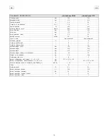
The total weight is 75 kg.
Packing dimensions:
Base: 78 cm x 40 cm
Height: 62 cm
ATTENTION:
Do not place more than 2 packings on top.
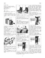
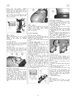
UNPACKING OF THE MACHINE
1. Open the packing as shown in the figure.
2. Take off the machine from the packing
avoiding heavy contacts to mechanical parts.
3. Keep the packing for eventual transport
needs.
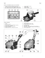
MOVEMENTS OF THE HANDLE BAR
The handle bar in the package arrives in
closed position.
To rotate the handle bar in one of the
different
working
positions enabling
the
movement of the machine:
1. Act upon the release lever (8) present
near the handle bars.
2. Rotate the handle bar into the working
position maintaining the release lever (8)
pressed.
3. Let go the release lever (8) to obtain the
blocakge of the handle bar.
Act in the same way for further height
adjustment of the handle bar in order to find
the most comfortable working position.
BATTERIES
This machine is supplied with two batteries
already connected in series, placed in its
appropriate compartment under the recovery
tank.
In case the batteries need to be disassembled
and/or replaced, please contact the authorized
technical assistance.
In fact, the replacement must be made
exclusively with batteries which have the
identical performances as the ones already
installed.
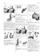
To reach the battery compartment it is
necessary to:
1. Take off the squeegee hose from its seat
(17).
2. Take off the suction filter cover (19) after
turning the blocking levers (18).
3. Lift and take off the recovery tank (16)
holding it from the provided handles obtained
one behind and the other in front of the tank.
ATTENTION:
Strictly follow manufacturer/distributor indications
for the maintenance and daily recharge of the
batteries. All installation and maintenance
operations must be executed by specialized
staff, using suitable protection accessories.
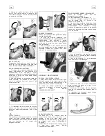
BATTERIES RECHARGING
(STANDARD VERSION WITH AGM
BATTERIES)
The charge level of the batteries is visible
activating first the general switch (1) placed
on the instrument board, through three
luminous leds placed on the frame in the rear
part of the machine.
A: green led on = batteries charged.
B: orange led on = level at half charge.
C: red led on = complete discharge of the
batteries with consequent automatic switching
off of all the machine's function.
In order not to cause permanent damages to
the batteries, it is essential to arrive to their
complete discharge every 6/7 cycles, providing
for the recharge only when the red signal of
discharged batteries is activated.
In fact, an extended series of charging cycles
carried out when the batteries still have a
residual charge, causes a battery deterioration
and a consequent charge and the battery itself.
NOTE: Never leave batteries completely
discharged even if the machine is not used.
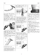
During the recharging operations a device is
activated that forbids the machine's functioning.
Bring the machine on a levelled surface near
to a single-phase socket type CEE 7/7, with
tension 230V, frequency 50Hz, nominal current
10A.
Switch off the general switch (1).
Connect the mains cable supplied with the
machine both to the machine and to the mains
socket as indicated in the figure.
At the end of the recharging phase take off
the mains cable.
BATTERIES RECHARGING
(PLUS VERSION WITH XFC BATTERIES)
The presence of a label with the writing
“plus”, placed on the frame in the rear part
of the machine, identifies the version equipped
with pure lead batteries (XFC) and its
suitable battery recharger.
The charge level of the batteries is visible
activating first the general switch (1) placed
on the instrument board, through three
luminous leds placed on the frame in the rear
part of the machine.
A: green led on = batteries charged.
B: orange led on = level at half charge.
C: red led on = complete discharge of the
batteries with consequent automatic switching
off of all the machine's function.
There is a phase in which the green led of
the general switch (1) starts to blink. This is
the best condition to carry out the battery
recharging with the possibility to continue to
work with the machine connected to the mains
system.
In fact this type of equipment contemplates a
battery recharger that supplies to the machine
a greater electric current than the required one
for the functioning of the machine. The
remaining current not used from the machine
provides for a slow recharging of the batteries.
For a faster recharging instead it is necessary
to stop working.


