


11
2.2
Electrical Installation
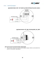
Two types of output are available from an Oval Gear flowmeter; NPN Hall Effect and Reed
Switch
(contact closure)
. Some meter configurations will have one of these outputs, some
will have both
;
a flowmeter may be installed using any of the available outputs.
2.2.1
Wiring
All wiring of electrical outputs should use high quality instrument cable; twisted pair low
capacitance shielded instrument cable
(20AWG [0.5mm
2
] minimum)
is recommended. Use
only high temperature cable where process temperatures exceed 185
o
F
(85
o
C)
. The cable
drain or screen should be terminated on a DC common or a specifically assigned shield
terminal at the readout instrument end only; in order to protect the signal from mutual
inductive interference.
The cable shield at the meter end of the cable must be isolated
with tape or similar, do not connect the cable shield to ground at the meter.
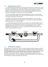
The cable should not be run in a common conduit, or parallel with, power cables or high
inductive load carrying cables; as interference will affect the transmitted pulse signal. Run
all instrument cables in their own separate conduit. Where instrument cables must cross
high power cables be sure that the cables intersect at 90 degrees in order to limit induced
interference.
Do not combine any inductive loads on the same voltage supply as your flowmeter wiring,
as these components are commonly sources of high frequency interference that may affect
the quality of the output signals. Inductive loads on a common voltage source also have the
potential for voltage spikes well in excess of the 24V (dc) limit of the flowmeter electronics.
The maximum wire cross section that can be connected to the terminals of an Oval Gear
pulse meter is 16AWG (1.5mm
2
).
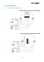
2.2.2
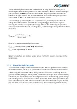
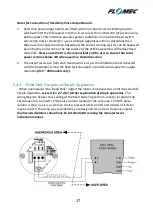
Hall Effect Outputs
The Hall Effect is a solid state 3 wire device which provides an open collector, NPN signal.
The output of the Hall Effect must be fitted with a pull-up resistor between the signal
output ( ) and the voltage supply. The Hall Effect output provides a square wave pulse
signal, which alternates between ground potential and the DC voltage available at the pull-
up resistor.
The NPN Hall Effect output is a reliable output type, producing a consistent output
irrespective of supply voltage variations, temperature variations, or mechanical shock. The
service life of the Hall Effect output is theoretically infinite, so long as it is protected from
high energy voltage spikes. Hall Effect outputs are protected against reverse polarity, and
against low energy voltage spikes; however, they are not protected against constant over-
voltage above the maximum limit of 24V (dc) (±5%).


