


OI. Read the installation manual
carefully before installation and
use.
11. Some models are not suitable for
drinking
water.
02. The manufacturer
will not be liable
for any personal injury, pump
damage and other property
damage due to failure to comply
with contents specified in safety
warning
signs.
12. The liquid may be high-temperature
and high-pressure; therefore, the
liquid in the system
m ust be
completely drained or the shut-off
valves on both sides must be
closed
before
moving
a nd
dismantling the pump to prevent
buming.
03. The installers and operators must
comply with local safety regulations.
04. The user must confirm that only
q ua lified
personnel
with
professionalcertification and
proficiency of this manual is
allowed to install and maintain this
product
13. If removing the exhaust bolt, high-
temperature and high-pressure
liquid will be overflew. Therefore.
it is necessary to insure that the
outflow liquid will not cause
personalinjury or damage other
para.
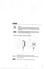
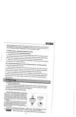
05. The pump must not be installed in a
place that is damp or may be
splashed
by water.
14. Ventilation must be ensured in
summer or high ambient
t e m p e rature period to avoid
condensation that may cause
electrical
malfunctions.
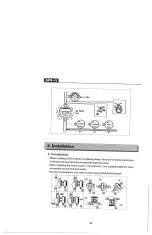
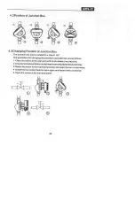
06. F=6r
convenient
access
of maintaince.
a shutoff valve
shall be installed
on
each side of the pump
15. In winter, the pump system does
not work or when the ambient
temperature drops below O "C
liquid in the system shall be
completely drained so as to avoid
frost cracking
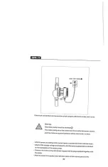
of pump body.
07. The power supply of the pump shall
be cut off before installation and
maintainace.
08. For domestic hot water, copper or
stainless steel pump body shall be
used.
16. If the pump is left unused for a long
time, please close the pir)e valve in
the inlet and outlet of the pump and
cut off the power supply.
09. Heatsupply pipelines shall not be
frequently filled with non-softened
water so as to avoid increasing
calcium in the circulating water
inside the pipeline. which may thus
block the impeller.
17.If he flexible cord of cable ist
damaged. it must be replaced by a
qualified
person.
10. Do not start the pump without liquid.
18. Please
close the valve at the inlet of
the pump and cut off power of the
pump immediately if overheating
01
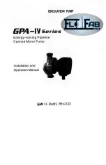
Summary of Contents for GPA-IV Series
Page 1: ......
Page 9: ...5 Electrical Connection 08...


