background image

432-0007-00-28-en-US  v100   

Integration with NMEA Devices – Application Note 


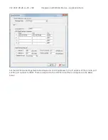
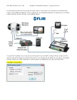
Set the UDP Mode Settings Destination Begin and End IP addresses to the IP address of the camera, and 
set the port number to 10001. These correspond to the UDP Terminal that is configured in the Radar 
Server. 


Summary of Contents for MV series

Page 1: ...Integration with NMEA Devices Application Note MV Series Thermal Cameras...

Page 2: ...guration 7 Radar Communications 8 Moxa NPort Server 9 Radar Server Configuration Changes 14 Using NMEA Mode 14 Multiple NMEA Devices 16 Troubleshooting 20 Unable to see radar tracks in FSM 21 Camera d...

Page 3: ...provided in this document have been tested by FLIR with the MV Series cameras Scope This document provides a brief guide to connecting and configuring the necessary components for using NMEA 0183 dev...

Page 4: ...munication protocol that enables navigation instruments and devices to exchange data with each other The NMEA 0183 Interface Standard defines electrical signal requirements data transmission protocol...

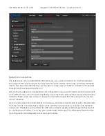
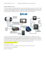
Page 5: ...a Serial to Ethernet Server is also connected to the PoE switch and this allows the radar communications to be sent to the camera Important Per the warning above the Ethernet connection from the came...

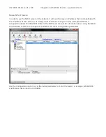
Page 6: ...can be used as a convenient tool for making configuration changes for monitoring the servers and devices and for troubleshooting communications issues In FSM each server will appear as a separate serv...

Page 7: ...the Radar Server is configured to receive the live location information and the Camera Server georeference can be associated with the Radar Server georeference Camera Configuration The factory configu...

Page 8: ...ion about the serial ports on the NPort server and on the radar Specifically ensure that both sides use the same signalling standard RS422 or RS232 baud rate and so on Ensure the transmitted signals f...

Page 9: ...of the camera so it is likely it will need to be changed In this example the NPort is assigned IP address 192 168 250 97 Refer to the NPort user manual for information about using the NPort Administr...

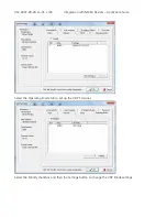
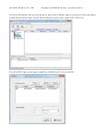
Page 10: ...00 28 en US v100 Integration with NMEA Devices Application Note Select the Operating Mode tab to set up the UDP Terminal Select the Modify checkbox and then the Settings button to change the UDP Mode...

Page 11: ...ith NMEA Devices Application Note Set the UDP Mode Settings Destination Begin and End IP addresses to the IP address of the camera and set the port number to 10001 These correspond to the UDP Terminal...

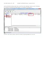
Page 12: ...Once the UDP Mode is set up it is possible to use the Port Monitor feature to confirm if the radar data is received by the NPort server Select the Port Monitor Option then select Add at the top Once t...

Page 13: ...Note Use the Port Monitor settings right click on one of the column headings to add a column that displays the number of transmitted and received packets for example Tx Rx after Mon Select the Go but...

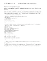
Page 14: ...68 250 97 UDP Port 10001 UDP Local Port 10001 Local IP Address eth0 Type UDP Terminal Confirm the IP Address and UDP Port correspond to the address and port of the NPort Serial server Sensor 1 RADAR C...

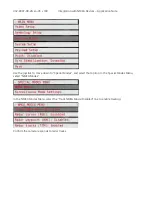
Page 15: ...pplication Note Use the joystick to move down to Special Modes and select that option In the Special Modes Menu select NMEA Modes In the NMEA Modes Menu select the Track NMEA Mode Disabled line to ena...

Page 16: ...the previous example refer to the manufacturer s documentation for configuration and wiring information about the serial ports on the NMEA mux Serial Ethenet server and other devices Specifically ensu...

Page 17: ...device The ShipModul MiniPlex 2E operates on 12 24VDC rather than PoE and can connect up to 4 NMEA talkers Connect the ShipModul mux to power and to the switch Use the MPX Config tool that comes with...

Page 18: ...le with a text editor as in the first example Perform a search of the file for Sensor 1 to locate the section related to the UDP Terminal Sensor 1 TERMINAL Configuration Device 0 Enabled yes IP Addres...

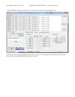
Page 19: ...vices Application Note In the ShipModul software select the Connect button to connect to the MiniPlex mux Verify if the mux is receiving NMEA data from the devices The image above shows GPGLL sentence...

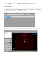
Page 20: ...the Radar Server If it has not already been done install and run FSM and use Setup Discovery to add the Camera and Radar Servers to the list of Active Sensors In FSM select View Tracks Panel confirm t...

Page 21: ...a goes through the initial pan tilt initialization when the power is turned on Be sure to allow time for the camera and the display to fully boot up and for the MFD to discover the camera When the cam...

Page 22: ...Commercial Systems Inc 70 Castilian Drive Goleta CA 93117 Phone 888 747 FLIR 888 747 3547 International 1 805 964 9797 www flir com Document Number 432 0007 00 28 en US Version 100 Issue Date October...

Reviews: